
ISE 21

V21.14.0 | 4th Nov 2021
ISE 21 User Guide |
V21.14.0 | 4th Nov 2021 | |
Intermorphic Sound Engine (ISE 21)
SF2 Modular MIDI Synth with Live FX
The Intermorphic Sound Engine (ISE) 20 is a MIDI-driven sound engine and is the latest iteration in our line of ISE engines. It comprises a framework of sound synthesis and fx technologies with associated design interfaces and goes beyond the traditional limitations of MIDI as it supports control of a number of essential fx units including Reverb, Delay, Distortion, Filtering etc.
The ISE is also a core component in Wotja and is driven by the Intermorphic (MIDI) Music Engine (IME).
The main contents of the ISE Guide are incorporated in the Wotja User Guide. The only extra information in this free-standing guide are the specialist sections on ISE Tutorials and the Glossary.
New in the ISE 21:
- NEW for ISE: Reverb 2XL FX unit (R2XL) - this awesome FX unit can also be combined with the new Pitch Shifter FX unit (below) for a Shimmer reverb effect; CPU intensive (not available in Synth Network)
- NEW for ISE: Pitch Shifter FX unit - used to shift the pitch of audio signal by +/- 12 semitones; CPU intensive (not available in Synth Network)
- NEW for ISE: Feedback option for Junction inputs (be *careful* with this!); used in the Shimmer FX presets
- NEW for ISE: ISE Audio Meter/Scope - To make sound design easier the Synth & FX Editor now has two new visual displays ("inspectors"), these being a meter for audio-rate units/junctions and an oscilloscope for control-rate units/junctions; Show or hide these inspectors with the new "Synth & FX Editor: Show Meter/Scope" toggle in Settings > General.
- NEW for ISE: ISE Unit "Bypass?" toggles - To make sound design easier ISE TG/Control/FX units now have a "Bypass?"" toggle and ISE Junction units have a "Bypass?" toggle in the junction toolbar; Bypassed units are marked with a subtle white X through the unit.
- IMPROVED: Synth & FX Editor shows left hand item to represent "input"
- IMPROVED: Synth & FX Editor uses arrow heads to illustrate direction of signal (rate) flow through the FX network; feedback lines are coloured orange; many other layout improvements
- IMPROVED: Reverb 1 max slider time increased to 20 seconds
- IMPROVED: Display "0-Network Input" rather than just "0" in ISE Synth & FX Editor controllers panel
- IMPROVED: Synth & FX button colour no longer uses Junction button colour if that is the first unit
- IMPROVED: Sliders (e.g. Scale) now have increased accuracy (1000 points up from 100 points).
- FIXED: FX Unit Wet/Dry modulation where if a value ever hit "zero" it would (for that cycle) pause the unit.
- FIXED: Bug in Amplifier unit which could cause glitching when adjusting / modulating pan.
- OTHER: See the Releases page for other improvements etc.
Apps that include the ISE 21:
- Wotja 21 - See the Wotja 21 User Guide
ISE Key Features
- Stereo audio pipeline for both Synth and FX networks.
- Network Editor for construction of modular synth and FX networks comprising:
- Sound/Tone Units (audio-rate): Macro Oscillator 1 (MO1), Wavetable (Soundfont [SF2] / DLS 1), Tone Generator (Osc), Drum Synth (DSynth), Particle Generator.
- FX Units (audio-rate): Filter, Reverb 1, Reverb 2XL, Pitch Shifter, Chorus, Delay, Distortion, Compressor, Overdrive, Amp, EQ.
- Controller Units (control-rate): LFO, Envelope, Amplifier.
- Junctions: Audio (audio-rate), Controller (control-rate).
- Includes the following SoundFont (SF2)/ DLS Wavetables: General MIDI, IM Calm. IM Drums, IM E-Perc, IM Guitar, IM E-Piano, IM Piano, IM Synths, IM NT-MT6 (deprecated, but for backwards compatability), IM NT3-MT7
- Wavetable Unit supports 16/24-bit mono/stereo SF2 wavetables.
- Supports a number of independently-specified synthesis modules per voice, as well as per-MIDI-line and global FX.
- Individual FX units in can be enabled, disabled, added, edited and deleted in real time, even while the music is playing.
ISE Editors
The ISE Synth & FX Editor is the primary ISE editing interface.
It is available in all Wotja apps and can be accessed via the Wotja Generator Network Panel as follows:
ISE Units^^
Synth (TG)
(Audio-rate)
FX
(Audio-rate)
Macro Oscillator 1 (TG)^
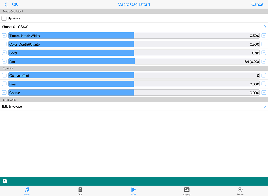
Macro Oscillator 1 - Tone Generator
Click image for large
This very powerful and complex modular synth unit is a port of the popular open-source "Braids" sound generator from Mutable Instruments (the github is here).
For information on its capabilities see the Mutable Instruments Documentation and/or PDF quickstart. You may also wish to look at the excellent http://www.vo1t.com/Euro/BraidsIllustrated1.8.pdf.
The best way to experiment with it is to load one of the many "MO1-Lead" patches that can be found from the Presets button.
As with any other ISE TG Unit it is a sound source for notes generated by the IME. This means it can be used polyphonically (you can set the polyphony required via the top Poly button in the Synth & FX Editor).
It can also be modulated via other control-rate units (LFO and Envelope modulators are shown in the screenshot) and can be used in a ISE Sound Network in combination with other TG and Control units.
Macro Oscillator 1 - Tone Generator (Audio-rate)^
- Bypass?: When this is checked the unit is bypassed.
- Shape: Choose from 47 different algorithms.
- Timbre: Sets a value for the algo's timbre.
- Colour: Sets a value for the algo's colour.
- Level: Sets the unit's output level.
- Pan: Sets the unit's stereo position.
Tuning
- Octave offset: This allows you to specify the octave offset from the voice's pitch.
- Fine: This allows you fine control over the pitch.
- Coarse: This allows you coarse control over the pitch.
Edit Envelope
The MO1 has its own integral envelope unit with the same capabilities as the Ctrl Envelope Unit.
- Delay: The length of time it takes after a note on event occurs for the voice, before the volume envelope starts to rise-up from zero to its Attack level.
- Attack: The length of time it takes after the delay time has passed for the voice, to rise-up from zero to its Attack level.
- Atk Level (Advanced): The target level for the attack stage of the envelope, as the envelope rises from its initial value of zero.
- Hold: The length of time it takes after the attack level is reached, before the envelope starts to decay down to the Sustain Level.
- Decay: The length of time it takes for the envelope to decay down from the Attack Level, down to the Sustain Level.
- Sustain: The level at which the note will play, once all of the Decay, Attack, and Hold periods have completed.
- Post Attack (Advanced): The length of time it takes after the note stop event occurs, for the envelope to move from the sustain level to the post-attack level
- Pst Atk Level (Advanced): The target level for the post-attack stage of the envelope, as the envelope moves from its sustain level.
- Post Hold (Advanced): The length of time it takes after the post attack level is reached, before the envelope starts to decay down to zero.
- Release: This time defines the time it takes for the Voice to respond to a note off event, in terms of how long it takes to decay from the Post-Attack Level to a level of zero.
DSynth (TG)^
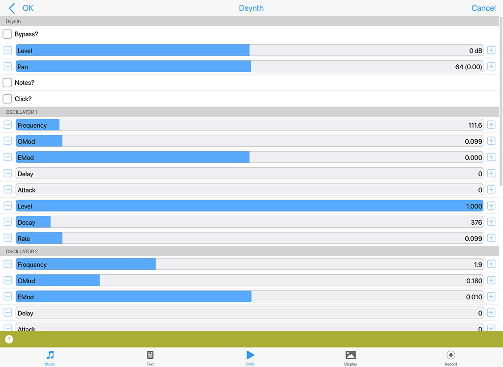
DSynth - Tone Generator
Click image for large
The "DSynth" tone generator unit can be used either as a melodic tone generator or as a Drum/Percussion Synthesizer for a range of drum/percussion related sounds. You can shift the pitch of the generated sound away from the notes that would otherwise be played, using the Tuning controls.
The unit works by combining two Oscillators which cross-modulate each other's oscillation frequency. Each oscillator has its own ADSR envelope which is used primarily to modulate the volume of the oscillator, but which can also be used to modulate the frequency of the oscillator!
The output of the two oscillators is merged with the output from a filtered noise generator (the bottom block of parameters) which also has its own ADSR envelope. The net effect is a unit which can create a wide array of percussive and melodic sounds. You can use the Export and Import buttons at the top of the unit to export and import DSynth settings to/ from the clipboard.
Tip: Use an audio junction unit to add together sounds from multiple tone generators to make even richer sounds!
DSynth - Tone Generator (Audio-rate)^
- Bypass?: When this is checked the unit is bypassed.
- Level: Sets the unit's output level.
- Pan: Sets the unit's stereo position.
- Notes?: This toggle determines whether the unit will actually use the composed note frequency to override the frequency of Oscillator 1. The default is that the checkbox is clear : i.e. the system will not use the composed note frequency for the unit. Tip : for percussive sounds, you might like to try clearing this checkbox!
- Click?: Use this toggle to add an initial transient when the notes are triggered; very useful for percussive sounds.
Oscillator 1 and Oscillator 2 Parameters
- Frequency: The frequency of oscillator 1 or 2.
- OMod: "Oscillator Modulation" - The amount of modulation provided by the other oscillator, for oscillator 1 or 2.
- EMod: "Envelope Modulation" - the amount of the envelope which should also be used to modulate the frequency of oscillator 1 or 2. If this is set to 0, then the ADSR envelope is used purely to modulate the volume of the oscillator.
- Delay: The length of time it takes after a note event occurs for the voice, before the envelope starts to rise-up from zero to its Attack level.
- Attack: The length of time it takes after the delay time has passed for the voice, for the envelope to rise-up from zero to its Attack level.
- A Level: The target Attack Level for the attack stage of the envelope, as the envelope rises from its initial value of zero.
- Decay: The length of time it takes for the envelope to decay down from the Attack Level, down to the Sustain Level of zero.
- Rate: A measure of the curvature of the Decay, down to the sustain level of zero. A value of 0 gives a linear decay, and increasing values giving an increasing level of curvature - resulting in a sound that is more "plucked" in nature.
Filter/Q Parameters
- Type List: The filter type to use: includes Low Pass, High Pass and Band Pass.
- Frequency: The frequency of the filter.
- Q: the amount of accentuation of the filter, 1.0 is high, 0.0 is no effect at all.
- EMod: "Envelope Modulation" - the amount of the envelope which should also be used to modulate the filter frequency. If this is set to 0, then the ADSR envelope is used purely to modulate the volume of the filtered noise..
- Delay: The length of time it takes after a note event occurs for the voice, before the envelope starts to rise-up from zero to its Attack level.
- Attack: The length of time it takes after the delay time has passed for the voice, for the envelope to rise-up from zero to its Attack level.
- A Level: The target Attack Level for the attack stage of the envelope, as the envelope rises from its initial value of zero. Tip: A value of zero is very good for melodic sounds; set to a higher value for more percussive sounds.
- Decay : The length of time it takes for the envelope to decay down from the Attack Level, down to the Sustain Level of zero.
- Rate: A measure of the curvature of the Decay, down to the sustain level of zero. A value of 0 gives a linear decay, and increasing values giving an increasing level of curvature - resulting in a sound that is more "plucked" in nature.
Tuning
- Octave offset: This allows you to specify the the octave offset from the voice's pitch.
- Semitone: This allows you to select the semitone offset from the voice's pitch (taking into account the octave offset above).
- Micro: This allows you to specify the microtonal offset in order to 'detune' the tone. -100 is the equivalent to a semitone down, and +100 is a semitone up.
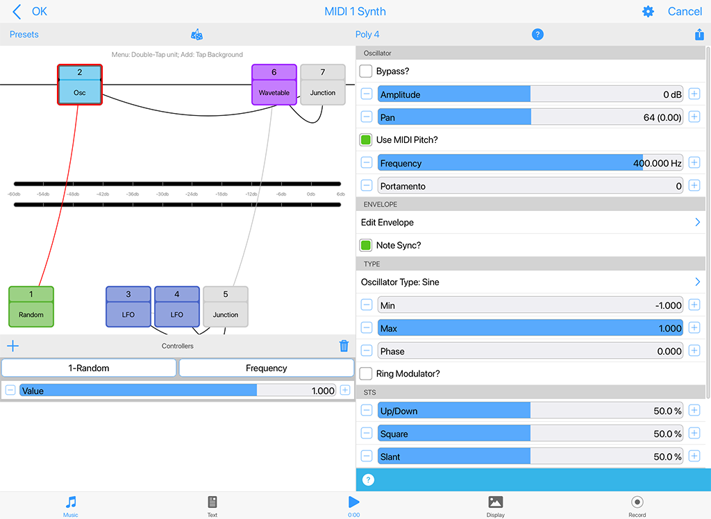
Osc (TG)^
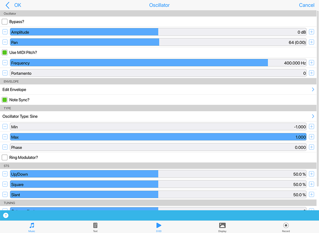
Osc - Tone Generator
Click image for large
This unit lets you create a range of waveforms, which are driven by MIDI pitch (via the "Pitch" checkbox); in which case, they are flexible, efficient MIDI tone generators.
Tip: You can use an audio junction unit to add together sounds from multiple tone generators to make even richer sounds!
Tip: The bottom linked Envelope Unit is there to help you shape your sound.
Osc - Tone Generator (Audio-rate)^
- Bypass?: When this is checked the unit is bypassed.
- Amplitude: Sets the amplitude of the generated waveform.
- Pan: Sets the unit's stereo position.
- Frequency: This controls the frequency of the unit, in Hertz (Hz, cycles per second).
- Portamento: This defines the amount of "pitch slide" (Portamento) from one note to the next; used when "Use Midi Pitch?" is selected. Basically a measure of the exponential approach to the pitch of the next note. Measured from 0 (minimum effect, an instantaneous change to the next note pitch) to 100 (maximum exponential approach to the target pitch).
Type
- Oscillator Type: This list includes Sine, Saw left, Saw right, Triangle, Square, STS (Saw, Triangle, Square) and Random. Change the Oscillator Type to dramatically change the sound of your Tone Generator.
- Sine produces a smooth waveform with no other harmonics.
- Saw Left and Saw Right produce waves that look like a saw-tooth close up. The either slope to the left or to the right, but sound identical (they are both provided, as combining these with other waveforms provide interesting effects due to their different phasing!).
- Triangle sounds not quite as harsh as the saw-tooth but has more harmonics than the sine.
- Square produces a 'square' looking wave and sounds rougher than either the sine or saw-tooth waves. With the square wave you have the option of specifying the ratio of the up portion of the wave to the down portion. At either extreme, the square wave becomes more like a pulse wave, giving a 'pulsing' sound at lower pitches.
- STS stands for 'Saw, Triangle, Square' because it is a hybrid between these three wave types. By varying the three parameters associated with it, the wave shape can be 'morphed' between the above three extremes. In effect, this waves covers all the preceding wave shapes, with the exception of the sine wave.
- Random produces white noise between Min and Max, also affected by the Amplitude. These values are produced irrespective of the pitch of the tone generator; and do not use the envelope of the tone generator. Random signals are particularly interesting when fed into filter effect units!
- Min: This defines the minimum value that the generated LFO waveform can have.
- Max: This defines the maximum value that the generated LFO waveform can have.
- Phase: useful for slow oscillators (e.g. 0.2 Hz) - determines the start point of the oscillator.
- Pitch: Select this checkbox if you want the MIDI pitch to determine the frequency of this tone generator. Use only for audio-rate units.
- Sync: Select this checkbox if you want the LFO to use the envelope to modulate the amplitude of the tone generator, or your own specific envelope settings that you can edit by pressing the "Edit Envelope" button. This only has any effect in Modular Synth networks, of course!
- Ring:TBA.
Particle (TG)^
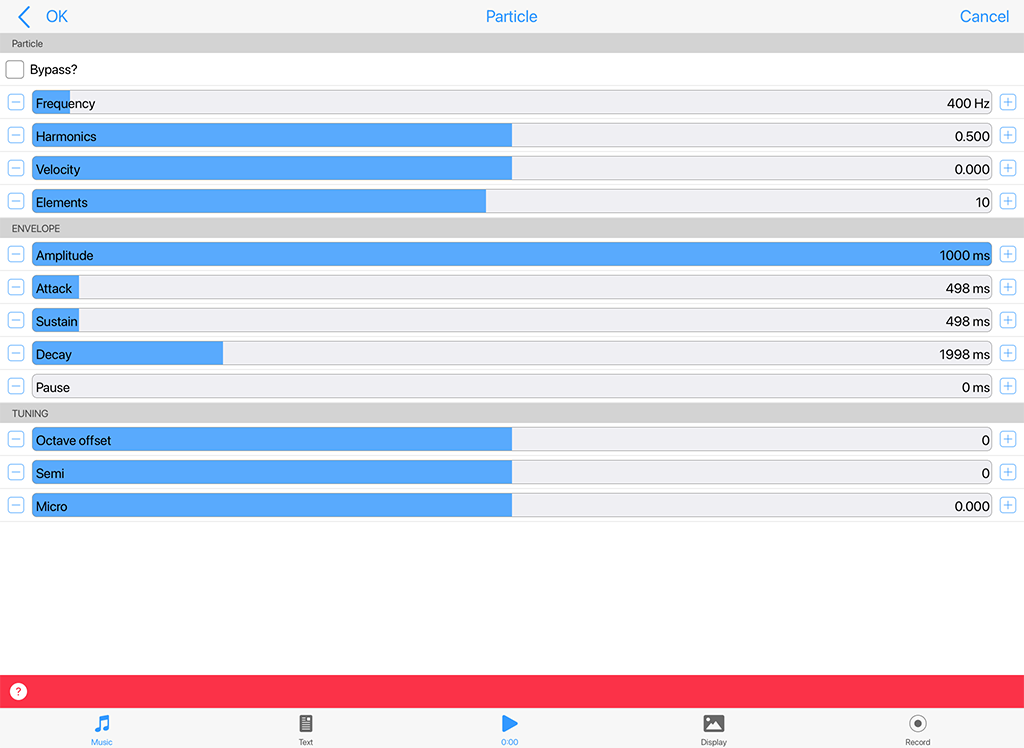
Particle - Tone Generator
Click image for large
DEPRECATED
This effect unit is an example of Granular Synthesis, which although is often used to do time-stretching of samples, is used for a completely different purpose here - that of creating rich layered sounds ranging from ambient forms to plopping sounds and twinkling chimes. The particle system incorporates octave, semitone and micro tonal offsets. It also has a checkbox that allows it to use the default volume envelope for amplitude shaping.
The Particle System synthesizes tones from a number of sine waves. This is really granular "additive synthesis". The unit works by streaming-out grains up to a maximum of 20 at any one time. These are randomly offset from each other to blend well. When the effect decides to generate a new grain, it takes its information from the dialog values. If the grains are reasonably large then the harmonics come in and out giving a full sound.
Tip: You can use an audio junction unit to add together sounds from multiple tone generators to make even richer sounds!
Particle - Tone Generator (Audio-rate)^
- Bypass?: When this is checked the unit is bypassed.
- Frequency: This controls the frequency of the internal high-frequency LFO, which is is used to modulate the "harmonics", giving a tone that is rich with harmonic information. Only used if "Use Notes?" is not set.
- Harmonics: Defines the range of multiples of the selected frequency present in the Particle System's output. What this means in plain English :) is that if you (say) have a frequency of 400Hz, and you define the Harmonic to be 3, then you may find grains with frequencies of 400, 800, and 1200 Hz in the generated waveform. The higher this value, the richer the harmonic output!
- Velocity: this scrollbar controls the change of frequency within any one grain. Try moving this a small bit and you will find the tones start to dive or soar - good for creating horror effects!
- Elements: The "number of elements" - the maximum number of grains present at any one time. The higher this value, the richer the output!
Envelope
- Amplitude: Defines the overall amplitude of the generated waveform.
- Attack / Sustain / Decay / Pause: Changing these settings modifies an internal envelope generator, which is used to alter the shape and duration of the grains. It is easy to get twinkling effects just by making the attack small (say 1) and the decay longer (say 200). The pause determines the gap between grains. Modulating harmonic, attack, and pan position gives a nice full sound that alternates between twinkling and blending.
Wavetable (TG)^
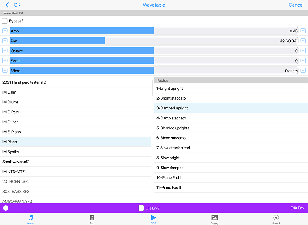
Wavetable - Tone Generator
Click image for large
Note: The Wavetable Unit is the unit that uses Soundfonts/SF2. It is also what you use if you want to use your own SF2, too.
When added to a Synth Network, a Wavetable Unit defaults to use the integral "General MIDI" (GM) SF2 Wavetable and plays Patch "001-Acoustic Grand Piano". To change the Patch select another one in the Patch list.
It is easy to use the other IM-included SF2 wavetables (IM Drums, IM E-Perc, IM Guitar, IM E-Piano, IM Piano, IM Synths).
Simply use the left list control to select the Wavetable from the list of those shown and then use the right hand list control to select the Patch (all patches available in the Wavetable are listed; they are listed in standard patch bank/patch order).
To use your own or 3rd party SF2, they just first need to be put in the right place (see: File Management - Where should I put or look for App Files, Zips, SF2, WAVs etc.?).
Note: If a Wavetable Unit is used in a Synth Network for a MIDI line, its Wavetable and selected patch will override the underlying piece's IME General MIDI Patch parameter (which always uses that patch in the GM Wavetable). If you DO want to use the piece's IME General MIDI Patch parameter setting, you must DELETE all units in the Synth Network and select the OK button to accept that. If you then re-enter the Synth Network you see a Wavetable Unit looks to have been added. It is a placeholder but it is not used - unless you enter the Wavetable unit in which case the sound will default to a GM Piano sound until you change it.
Top Tip: There are 4 parameters in the Wavetable unit that can be modulated: Frequency, Portamento, Amp and Pan. Try using a LFO Unit to modulate the Wavetable Unit's frequency paramater to apply a vibrato effect. To change how that vibrato is applied over time, try shaping the output of the LFO with an Envelope Unit before feeding into the Wavetable Unit.
Tip: You can use an audio junction unit to add together sounds from multiple tone generators to make even richer sounds.
Wavetable - Tone Generator (Audio-rate)^
- Bypass?: When this is checked the unit is bypassed.
- Amp: Used to set the unit's output level.
- Pan: Used to set the unit output's pan position.
- Ove: This allows you to specify the the octave offset from the voice's pitch. NB: To see this control you need to scroll down the top area.
- Semi: This allows you to select the semitone offset from the voice's pitch (taking into account the octave offset above). NB: To see this control you need to scroll down the top area.
- Micro: This allows you to specify the microtonal offset in order to 'detune' the tone. -100 is the equivalent to a semitone down, and +100 is a semitone up.
Selector List
- SF2/DLS List (left): Used to select the Wavetable.
- Patches List (right): Used to select the Patch in the Wavetable.
Bottom Toolbar
- Envelope Toggle: If on, the settings of the integral Envelope are applied. If off, the envelope values are ignored.
- Envelope: The Wavetable unit has an integrated Envelope Unit which can be used to shape it's sounds. This is a very powerful feature that can be used for sound design (e.g. long attack and post release sounds).
Amp (FX)^
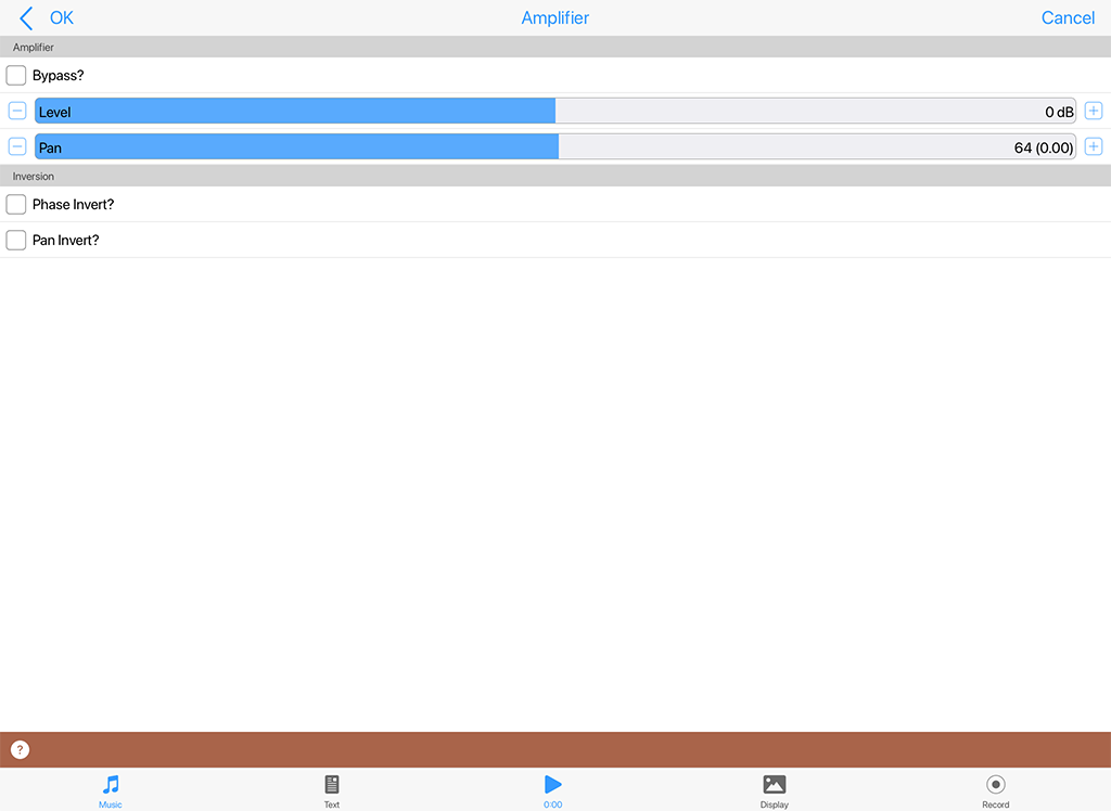
Amp - FX
Click image for large
If you have a weak signal, e.g. coming out from a Filter Unit or an Wavetable Unit, then pump it into an amplifier. The Amplifier can multiply the input by a factor of up to 10. If you want more than this, feed it into another amplifier!
Amp - FX (Audio-rate)^
- Bypass?: When this is checked the unit is bypassed.
- Level: Determines the amount of amplification to be done by this amplifier unit. The default value is 1.00 (0dB - i.e. no amplification) and values can range from 0, 0.10 (-19dB) to 10.00 (20dB)
- Pan: Determines the pan position of the signal. The default value is 64 (center).
- Phase Invert?: When on, the phase of the signal will be inverted.
- Pan Invert?: When on, the pan of the signal will inverted.
Chorus (FX)^
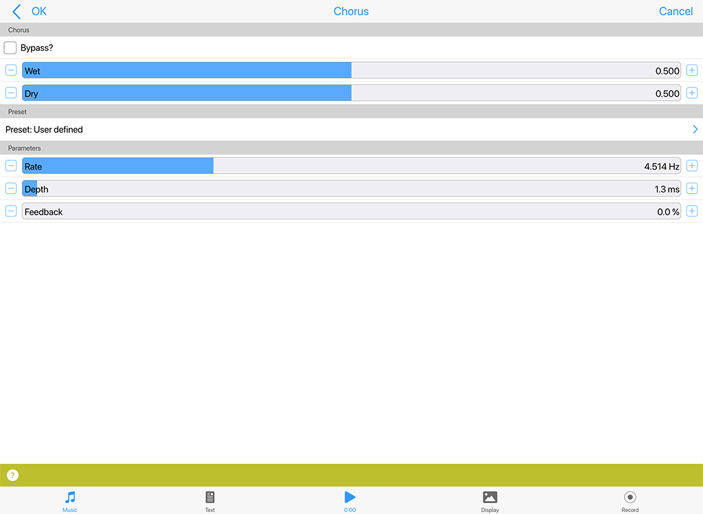
Chorus - FX
Click image for large
Sums the input and duplicates it at varying delay rates with the effect of "thickening" the audio. The delay time and frequency should be tweaked to give the right feel.
Chorus - FX (Audio-rate)^
- Bypass?: When this is checked the unit is bypassed.
- Wet: Adjust this value to alter the amount of "wet" (processed) signal in the mix.
- Dry: Adjust this value to alter the amount of "dry" (unprocessed) signal in the mix.
- Preset: Use this to apply a "macro" setting of chorus parameters.
- Rate: A measure of the chorus modulation rate, in Hertz.
- Depth: A measure of the chorus modulation depth, in milliseconds.
- Feedback: The amount of Chorus Modulation Feedback to apply, as a percentage from 0 to 100 (which is the maximum).
Compressor (FX)^
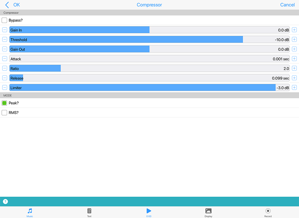
Compressor - FX
Click image for large
Used to help compress the signal in the DSP chain.
If you view the compressor behaviour as a function of Output (measured in decibels [dB]) against Input (measured in decibels [dB]), the compressor displays three distinct regions of behaviour:
- Linear with a slope of 1 up to the Compression Threshold (CT)
- Compressor with a slope of 1/CR (where CR is the Compression Ratio) up to the Limit Threshold (lT)
- Limiter with a slope of 0 from the Limit Threshold (lT) and beyond
Compressor - FX (Audio-rate)^
- Bypass?: When this is checked the unit is bypassed.
- Gain In: Input gain setting; defaults to 0 dB.
- Threshold: This is the input/output level where the compressor becomes active. Below this level input = output.
- Gain Out: Output gain setting; defaults to 0 dB.
- Attack: This determines how quickly the envelope will respond to a positive change in the signal level. The value indicates the time it takes the envelope to rise 50% of the change.
- Ratio: Determines the compression ratio. If this value is < 1 it will in effect work as an expander.
- Release: This determines how quickly the envelope will respond to a negative change in the signal level. The value indicates the time it takes the envelope to fall 50% of the change.
- Level Detect Mode: This has one of two values, which determines whether the signal is compressed/limited according to the peak or RMS level of the signal.
- Limiter: The output is limited to this level. If this value is lower than dBCompThreshold, the compressor will not be in operation.
Mode
- Peak: Use Peak signal
- RMS: Use RMS signal
Delay (FX)^
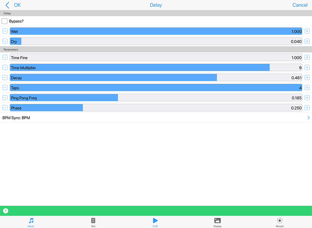
Delay - FX
Click image for large
Used to add interesting delay effects to an audio signal.
Delay - FX (Audio-rate)^
- Bypass?: When this is checked the unit is bypassed.
- Wet: Adjust this value to alter the amount of "wet" (processed) signal in the mix.
- Dry: Adjust this value to alter the amount of "dry" (unprocessed) signal in the mix.
- Time Fine: This parameter quickly determines the gross delay time in multiples of two. Increasing this parameter by one stop doubles the delay time, decreasing it halves it.
- Time Multiplier: This parameter allows the user to fine tune the delay time in between the multiples specified by the parameter above.
- Decay: This determines the amplitude attenuation with each passing delay tap.
- Taps: The number of "taps" in the delay system : the greater this number, the greater is the "thickness" of the delay effect.
- Ping Pong Freq: Frequency (Ping Pong) is the movement across the stereo field with each passing delay tap. A high Ping-Pong frequency ensures a 'Ping-Pong' type of effect from one channel to the other. A low frequency results in a type of drift from one channel to the other. Only applies if the Delay is applied to a stereo signal pipeline.
- Phase: This simply determines where in the stereo field the Ping-Pong starts. Only applies if the Delay is applied to a stereo signal pipeline.
- BPM Sync: Default (non-tempo synched option) and various BPM values, e.g. BPM/4 which means generate the waveform selected in the above list at a tempo of the mix tempo (BPM)/4. This control allows for tempo-synched control of the Delay unit, for great effect.
Distortion (FX)^
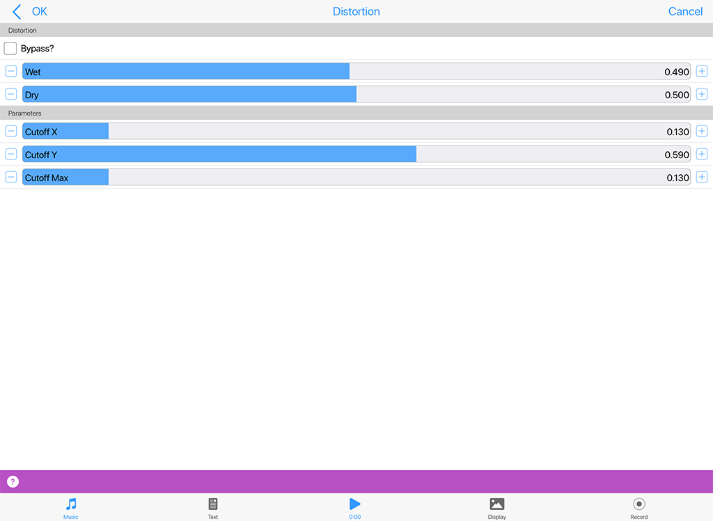
Distortion - FX
Click image for large
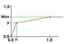
Distorts the sum of your incoming signals. Take cutoff X right down to about 0.02 to get a really distorted sound - it sounds great on a particle system! Cutoff Y acts like an amp and Cutoff Max determines the position of the output wave when the input is at 1.0 or -1.0.
The combination of Cutoff X, Y and Cutoff Max contribute to reshaping the input signal.
Graph of the Distortion Cutoff parameters
Distortion - FX (Audio-rate)^
- Bypass?: When this is checked the unit is bypassed.
- Wet: Adjust this value to alter the amount of "wet" (processed) signal in the mix.
- Dry: Adjust this value to alter the amount of "dry" (unprocessed) signal in the mix.
- Cutoff X: This determines the input value which will be scaled to the output value of 'y'.
- Cutoff Y: As above, i.e. at input 'x', 'y' is the output.
- Cutoff Max: At input value of 1.0, the output is 'Max'. Max may even be set to be lower than Cutoff Y
Equaliser (FX)^
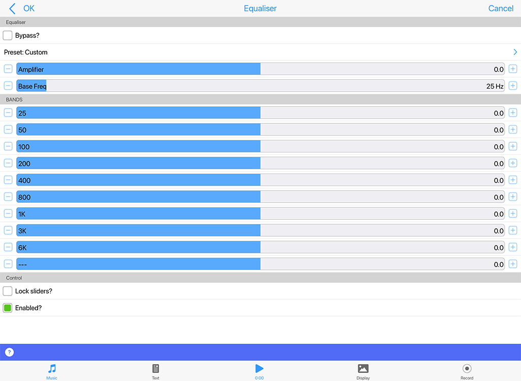
Equaliser - FX
Click image for large
Use the Equaliser Unit to modify the frequency response of your audio signal. Depending on how you configure the unit, it can operate as either a 5-band or a 10-band equaliser. Note that the 5-band equaliser takes less CPU power.
Equaliser - FX (Audio-rate)^
- Bypass?: When this is checked the unit is bypassed.
- Preset: Select from a range of presets.
- Amplifier: Specifies the amount of pre-amplification applied to the equaliser input signal. Adjusts from -20 dB to +20 dB.
- Base Freq: This slider adjusts the frequency of the lowest EQ band. All other sliders will automatically follow to maintain the frequency ratio between bands.
- EQ bands: Specify the gain for the indvidual frequency bands. Adjust from -14 dB to +14 dB. Unused frequency bands will display "N/A" in case of 5-band EQ mode, or if band frequencies are close to or above half the sample frequency.
Toolbar
- Lock checkbox: Use to allow all sliders to move together at the same time when you change any one of the individual slider values.
- On/Off checkbox: Use this to enable or disable the EQ
Filter (FX)^
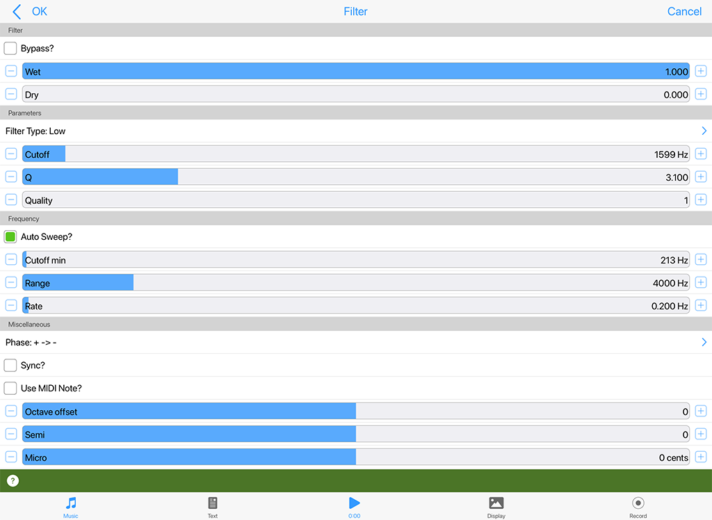
Filter - FX
Click image for large
The Filter Unit can work in a variety of different ways depending on how you configure it:
- Using a fixed filter frequency
- Using a built-in frequency sweep
- Using a filter frequency that is adjusted dynamically such that it tracks currently playing note pitches.
Filter - FX (Audio-rate)^
- Bypass?: When this is checked the unit is bypassed.
- Wet: Adjust this value to alter the amount of "wet" (processed) signal in the mix.
- Dry: Adjust this value to alter the amount of "dry" (unprocessed) signal in the mix.
- Filter Type: A list that includes Low Pass, High Pass and Band Pass.
- Cutoff: Determines the minimum frequency for the built-in filter frequency sweep
- Q: The amount of accentuation (resonance) of the filter, 1.0 is the lowest value, and provides low quality filtering with little resonance, 5.0 provides high quality filtering with high resonance, and 10.0 provides the greatest resonance.
- Quality: The number of cascaded 12 dB/octave filter sections, defaults to 1. Use a higher value to get sharper cutoff, at the cost of greater CPU consumption.
- Auto Sweep?: This toggle determines whether or not the built-in filter frequency is in use. When not selected, this checkbox disables automatic filter sweeping.
- Cutoff min: Determines the cutoff or center frequency for the filter in Hertz.
- Range: This value, when added to the Filter Cutoff Min determines the upper frequency for the built-in filter frequency sweep
- Rate: Determines the rate in Hertz at which the filter sweep moves from minimum to maximum value (and back again) [Sweep check box must be checked].
- Phase: Determines the phase used by the built-in frequency sweep.
- Sync?: Only relevant when the filter is used with IME part.
- Freq?: When this toggle is set, the filter frequency actually follows the currently played note pitch, where the note is generated by the IME. Tip: setting this checkbox gives a tonal quality to the Filter effect. In this case, the following parameters apply:
- Octave Offset: This combo-box allows you to specify the octave offset from the current note pitch
- Semi: This allows you to select the semitone offset from the current note pitch (taking into account the octave offset above) if Use Notes is set).
- Micro: This allows you to specify the microtonal offset in order to 'detune' the filter. The value supplied is in cents (1 cent = 1/100 semitone).
Overdrive (FX)^
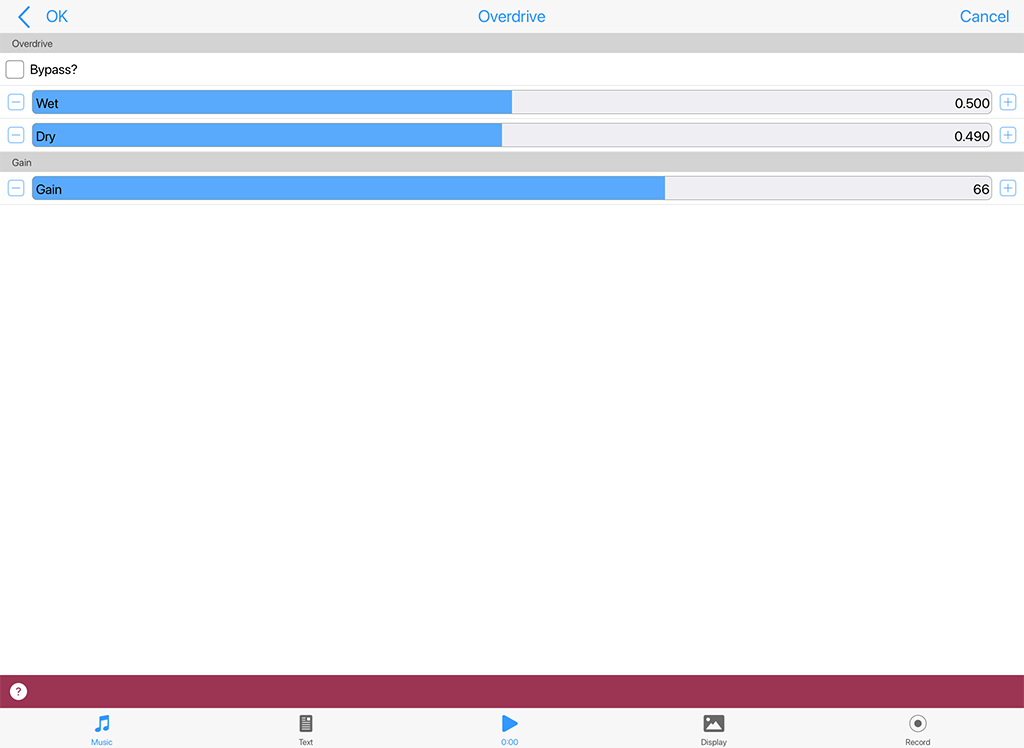
Overdrive - FX
Click image for large
This unit adds overdrive distortion to the sound source.
Overdrive - FX (Audio-rate)^
- Bypass?: When this is checked the unit is bypassed.
- Wet: Adjust this value to alter the amount of "wet" (processed) signal in the mix.
- Dry: Adjust this value to alter the amount of "dry" (unprocessed) signal in the mix.
- Gain: Determines the amount of overdrive (distortion) applied.
Pitch Shifter (FX)^
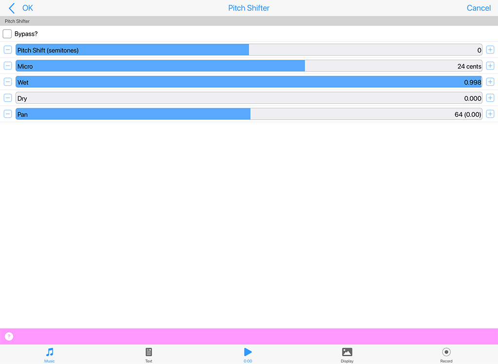
Pitch Shifter - FX
Click image for large
This unit allow the pitch of the input to be live-shifted (there is a small latency) by up to a maximum of +/- 12 semitones.
The parameters that can be modulater (by a control-rate unit) are: Dry, Wet, Pan and Micro.
Pitch Shifter - FX (Audio-rate)^
- Bypass?: When this is checked the unit is bypassed.
- Pitch Shift (semitones): The amount of pitch shifting you want to occur in semitones (up to +/- 12).
- Micro: This allows you to specify the microtonal offset in cents (1 cent = 1/100 semitone).
- Wet: Adjust this value to alter the amount of "wet" (processed) signal in the mix.
- Dry: Adjust this value to alter the amount of "dry" (unprocessed) signal in the mix.
- Pan: Adjust this value to alter the pan of the output in the mix.
Reverb 1 (FX)^
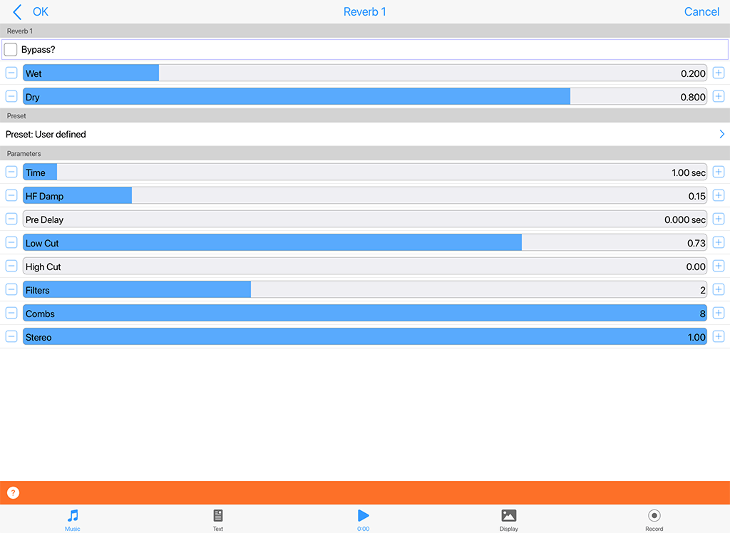
Reverb 1 - FX
Click image for large
This unit adds reverberation to the sound. This gives depth to the sound and makes it seem as though the piece is being performed in a room. You can control the 'size' and sound of this room with the parameters below.
Reverb 1 - FX (Audio-rate)^
- Bypass?: When this is checked the unit is bypassed.
- Wet: Adjust this value to alter the amount of "wet" (processed) signal in the mix.
- Dry: Adjust this value to alter the amount of "dry" (unprocessed) signal in the mix.
- Preset: Select from a range of presets.
- Time: Determines the duration of the reverb.
- HF Damp: In most environments high frequencies will attenuate more quickly than low frequencies due to damping caused by carpets, furnishings, etc. Use this control to adjust the amount of high frequency damping.
- Pre Delay: Delay of reverb relative to the dry (unprocessed) signal.
- Reverb Type List: Choose the reverb type from a number of musical and environmental presets.
- Low Cut: Applies a lowpass filter to the reverberated sound. The value is the normalised cutoff frequency of the filter, with "1.00" corresponding to half the sample frequency (at 1.00 no lowpass filtering is applied).
- High Cut:Applies a highpass filter to the reverberated sound. The value is the normalised cutoff frequency of the filter, with "1.00" corresponding to half the sample frequency (at 0.00 no highpass filtering is applied).
- Combs: Determines the number of parallel comb filters used in the reverb algorithm. A higher number generates a more dense reverb tail, but is also more CPU intensive.
- Filters: Determines the number of series allpass filters used in the reverb algorithm. A higher number generates a smoother reverb tail, but is also more CPU intensive.
- Stereo: Adjust this value to change the perceived "width" of the sound.
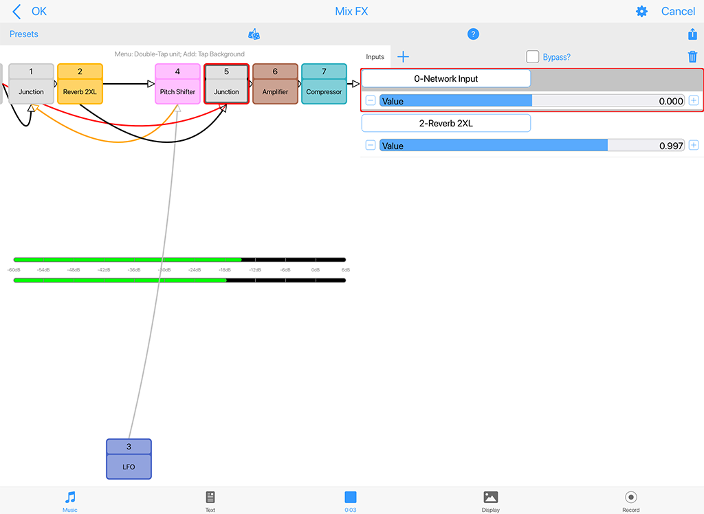
Reverb 2XL (FX)^
Reverb 2XL - FX
Click image for large
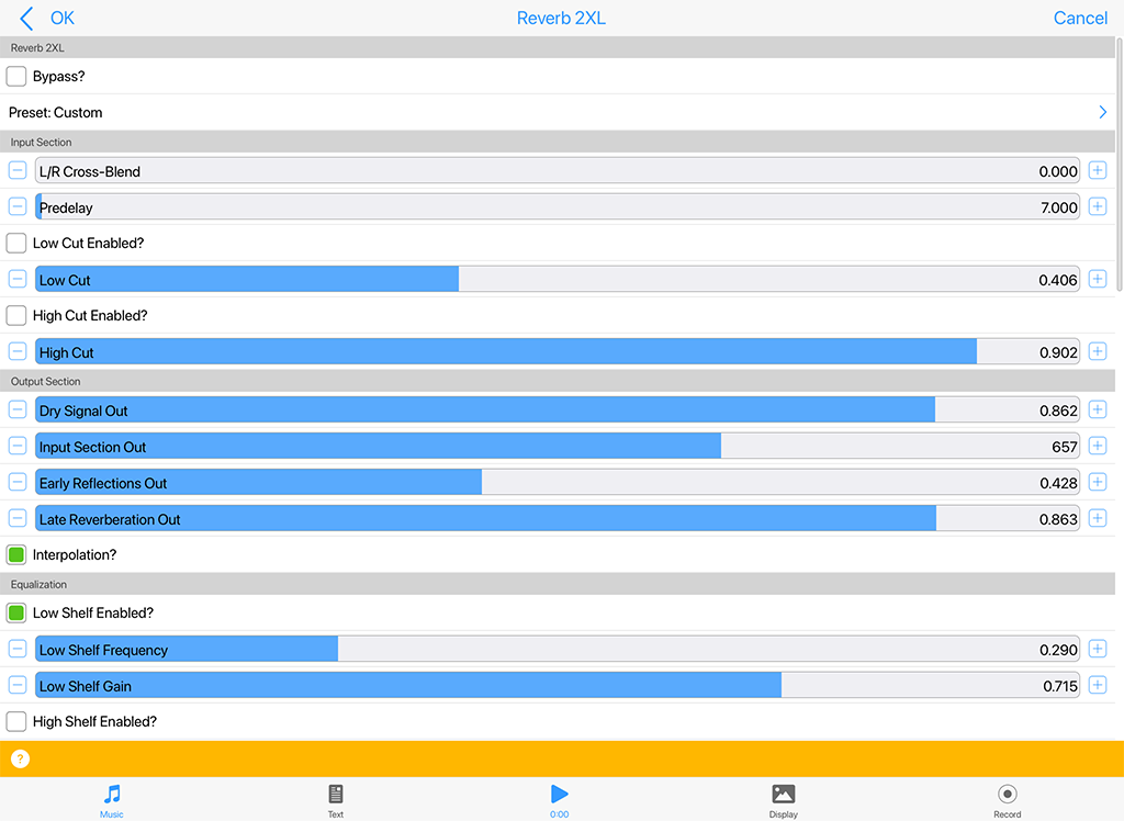
This unit adds a complex reverberation to the sound and gives it a deep richness, but at the cost of more CPU processing than with Reverb 1. There are many parameters to explore.
The unit is based on the Cloud Seed Reverb unit, see the link for full documentation. We will be adding abbreviated details soon.
Reverb - FX 2XL (Audio-rate)^
- Bypass?: When this is checked the unit is bypassed.
- Preset: Select from a range of included presets.
- Input Section:
- L/R Cross-Blend (0-1):
- Predelay (0-1000ms):
- Low Cut Enabled?:
- Low Cut (0-1):
- High Cut Enabled?:
- High Cut(0-1):
-
Output Section:
- Dry Signal Out (0-1):
- Input Section Out (0-1):
- Early Reflections Out (0-1):
- Late Reflections Out (0-1):
- Interpolation?:
- Equalization:
- Low Shelf Enabled?:
- Low Shelf Frequency (0-1):
- Low Shelf Gain (0-1):
- High Shelf Enabled?:
- High Shelf Frequency (0-1):
- High Shelf Gain (0-1):
- Cutoff Enabled?:
- LP Cutoff Frequency (0-1):
- Stereo Width (0-1):
- Early Reflections - Delays:
- Tap Count (0-1):
- Tap Length (0-500ms):
- Tap Gain (0-1):
- Tap Decay (0-1):
- Tap Seed (0-1m):
- Early Reflections - Diffuser:
- Enabled?:
- Delay (0-1):
- Feedback (0-1):
- Mod Amount (0-2.5):
- Mod Rate (0-1):
- Stages (0-8):
- Diffusion Seed (0-1m):
- Late Reverberation:
- Lines in Parallel (1-12):
- Late Reverberation - Delay:
- Time (0-1):
- Line Decay (0-500ms):
- Mod Amount (0-2.5):
- Mod Rate (0-1):
- Tap: Pre/Post (on = Pre; off = Post)?:
- Delay Seed (0-1m):
- Late Reverberation - Diffuser:
- Enabled?:
- Delay (0-1):
- Feedback (0-1):
- Mod Amount (0-2.5):
- Mod Rate (0-1):
- Stages (0-8):
- Diffusion Seed (0-1m):
- Wet: Adjust this value to alter the amount of "wet" (processed) signal in the mix.
- Dry: Adjust this value to alter the amount of "dry" (unprocessed) signal in the mix.
Envelope (Ctrl)^
Envelope - Controller
Click image for large
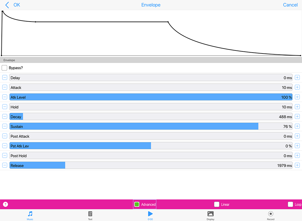
The Envelope Unit is used to edit the "Ctrl-Envelope" control-rate plugin. It is only of use in Modular Synth networks, where it is triggered in response to MIDI note on events for the current MIDI line, and generates no sound of its own. Used in context of the TG Osc it is also triggered in response to MIDI note off events.
Note: An Envelope Unit can be added to an FX Network, but it cannot be used to modulate an FX and can even mute the sound - so we do not recommend doing it!
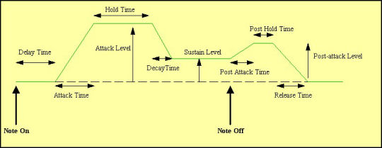
There are a number of values which you can adjust to modify the shape of your envelope. The shape used is shown in this diagram below.
Envelope - Controller (Control-rate)^
- Delay: The length of time it takes after a note on event occurs for the voice, before the volume envelope starts to rise-up from zero to its Attack level.
- Attack: The length of time it takes after the delay time has passed for the voice, to rise-up from zero to its Attack level.
- Atk Level (Advanced): The target level for the attack stage of the envelope, as the envelope rises from its initial value of zero.
- Hold: The length of time it takes after the attack level is reached, before the envelope starts to decay down to the Sustain Level.
- Decay: The length of time it takes for the envelope to decay down from the Attack Level, down to the Sustain Level.
- Sustain: The level at which the note will play, once all of the Decay, Attack, and Hold periods have completed.
- Post Attack (Advanced): The length of time it takes after the note stop event occurs, for the envelope to move from the sustain level to the post-attack level
- Pst Atk Level (Advanced): The target level for the post-attack stage of the envelope, as the envelope moves from its sustain level.
- Post Hold (Advanced): The length of time it takes after the post attack level is reached, before the envelope starts to decay down to zero.
- Release: This time defines the time it takes for the Voice to respond to a note off event, in terms of how long it takes to decay from the Post-Attack Level to a level of zero.
Toolbar
- Reset: Sets the envelope back to default values.
- Linear: This toggle lets you set both Decay and Release stages to either Linear or Exponential.
- Advanced: When toggled on, you can see some extra controls, indicated above as "Advanced".
LFO (Ctrl)^
LFO - Controller
Click image for large
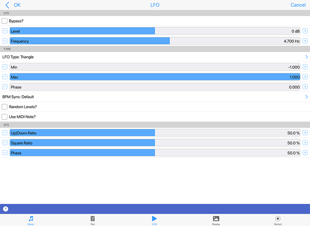
This unit lets you create a range of control-rate waveforms. The waveforms oscillate at a pitch that you dictate yourself. They are used for modulating the parameters of other effect units; they should only be run below (say) 50Hz or you'll get some odd effects.
LFO - Controller (Control-rate)^
- Bypass?: When this is checked the unit is bypassed.
- Level: Sets the amplitude of the generated LFO waveform.
- Frequency: This controls the frequency of the LFO, in Hertz (Hz, cycles per second).
Type
- LFO Type: This list includes Sine, Saw left, Saw right, Triangle, Square, STS (Saw, Triangle, Square) and Random. Change the LFO Type to dramatically change the sound of your LFO.
- Sine produces a smooth waveform with no other harmonics.
- Saw Left and Saw Right produce waves that look like a saw-tooth close up. The either slope to the left or to the right, but sound identical (they are both provided, as combining these with other waveforms provide interesting effects due to their different phasing!).
- Triangle sounds not quite as harsh as the saw-tooth but has more harmonics than the sine.
- Square produces a 'square' looking wave and sounds rougher than either the sine or saw-tooth waves. With the square wave you have the option of specifying the ratio of the up portion of the wave to the down portion. At either extreme, the square wave becomes more like a pulse wave, giving a 'pulsing' sound at lower pitches.
- STS stands for 'Saw, Triangle, Square' because it is a hybrid between these three wave types. By varying the three parameters associated with it, the wave shape can be 'morphed' between the above three extremes. In effect, this waves covers all the preceding wave shapes, with the exception of the sine wave.
- Random produces white noise between Min and Max, also affected by the Amplitude. These values are produced irrespective of the pitch of the tone generator; and do not use the envelope of the tone generator. Random signals are particularly interesting when fed into filter effect units!
- Note On Random means that every time a note on event occurs, the random value changes, and sits there until the next note on event occurs. The value then sits there, until the next note on event - when the value is changed again.
- Min: This defines the minimum value that the generated LFO waveform can have.
- Max: This defines the maximum value that the generated LFO waveform can have.
- Phase: Useful for slow oscillators (e.g. 0.2 Hz) - determines the start point of the oscillator.
- BPM Sync: Default (non-tempo synched option) and various BPM values, e.g. BPM/4 which means generate the waveform selected in the above list at a tempo of the mix tempo (BPM)/4. This control allows for tempo-synched control of e.g. the Filter unit, for great effect.
- Random Levels?: When checked, creates random control values bounded between the settings of the Min and Mix knobs. If a BPM setting is chosen in the Freq List, then these values will change at that control rate for a "sample and hold" effect.
- Use MIDI note?: Applies the waveform each time a MIDI note is played.
STS
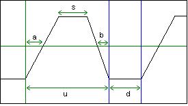
The STS Waveform and its ratios
- U/D: Only for the Square and STS wave types. Defines the ratio of "Up" to "Down" (or "On" to "Off") values (for STS waveforms, this is the ratio of u to d in the diagram below).
- Sqr: Only for the STS wave type. Defines the "squareness" of the waveform (the ratio of s to u in the diagram below).
- Slant: Only for the STS wave type. Defines the skew of the waveform (the ratio of a to a + b in the diagram below)
- With the Up Down Ratio at 100.0%, the Squareness Ratio at 0.0% and the Slant Ratio at 50.0%, the shape is a triangle.
- With the Up Down Ratio at 100.0%, the Squareness Ratio at 0.0% and the Slant Ratio at 0.0% or 100.0%, the shape is a Saw Right or Saw Left respectively.
- Lastly, with the Up Down Ratio at 100.0%, the Squareness Ratio at 100.0% and the Slant Ratio at anything you please, the shape is a Square wave.
Amp (Ctrl)^
Amp - Controller
Click image for large
If you have a weak control rate signal, coming from a LFO for example, then pump it into an amplifier. The Amplifier can multiply the input by a factor of up to 10. If you want more than this, feed it into another amplifier!
Amp - Controller (Control-rate)^
- Bypass?: When this is checked the unit is bypassed.
- Level: Determines the amount of amplification to be done by this amplifier unit. The default value is 1.00 (0dB - i.e. no amplification) and values can range from 0, 0.10 (-19dB) to 10.00 (20dB)
- Pan: Determines the pan position of the signal. The default value is 64 (center).
- Phase Invert?: When on, the phase of the signal will be inverted.
- Pan Invert?: When on, the pan of the signal will inverted.
Random (Ctrl)^
Random - Controller
Click image for large
This unit simply generates a random value from -1 to +1 at the control rate (it is not an audio unit). There is no Unit interface, but you control the scale factor with the slider at the bottom of the Network Screen.
Random - Controller (Control-rate)^
- Connector: The "Connector" list lets you select the effects unit (which must be a control-rate unit) that is modulating the parameter for your effects unit. Change the entry here to be the unit number of the control-rate unit that you want to modulate your effects unit.
- Controller: The "Controller" list shows you a count of all the effects unit inputs that modulate parameters of your currently selected effects unit. The numbers in the list are just always numbered automatically from 1 upwards. Note that if there are no entries shown in the "Param" list, then this effect unit has no available modulators, and therefore you have nothing to control on it from e.g. LFOs or envelopes (in which case, Add etc. will have no effect).
- Add: Press the "Add" button to add a new entry to your "Controller" list.
- Delete: Press the "Delete" button to remove the currently selected Controller list item.
- Scale: The "Scale" slider lets you fine-tune a scaling factor between -2 and 2, by which the modulating input value (from the modulating unit) is multiplied, before being applied to your modulated effect unit's parameter. This allows you to carefully adjust the amount by which a parameter is modulated. Note that if more than one control-rate unit feeds a specific parameter on a target unit, they will get added together automatically (including the appropriate scaling factor); which means that control-rate junctions are not often required. Double tap or right mouse click the Scale slider for a pop-up menu with the following options:
- Edit: Enter the value you want to use in the pop-up text field.
- Default: Sets the value to 1.
- Zero: Sets the value to 0.
- Random: Sets the value to some random value between -2 and 2.
- Modulate Parameter: The "Modulate Parameter" list lets you select the effects parameter that you want to be modulated by the specified control-rate unit!
Junction^
Junction Unit
Click image for large
Audio-rate / Control-rate
Junction units are what you use whenever you need to add or combine together the output from two or more units in the system. They are added from the Units drop list below the Chain display. They are shown in grey in the network and have no interface of their own.
There are two types:
- Junction: Audio-rate junctions for Tone Generators and FX (and available only in Synth networks). Use these when you need to add-together outputs from two or more audio-rate units. They display in the top "audio-rate" line of the network
- Ctrl-Junction: Control-rate junctions for Controllers (available in both Synth and FX networks). Use these when you need to add-together outputs two or more control-rate units. They display in the bottom "control-rate" line in the network
When a junction unit is selected in the top "Chain" display area, a "Connector + Unit" section displayes at the bottom of the Network Editor screen and which lets you change junction inputs.
Junction - Audio-rate / Control-rate^
Connector + Unit & Scale: These only show if your currently selected unit is a audio-rate [audio] junction ("Junction") or a control-rate junction ("Ctrl-Junction").
- Bypass?: When this is checked the junction unit is bypassed.
- Connector: The "Connector" list shows you a count of all the effects unit inputs that are fed-in to your junction. The numbers in the list are just always numbered automatically from 1 upwards.
- Unit: The "Unit" list lets you select the effects unit (which must be a unit at the same rate as the junction!) that is to be added together to help create the output of the junction. Change the entry here to be the unit number of the unit that you want to add with other unit outputs.
- Add: Press the "Add" button to add a new entry to your "Input" list.
- Delete: Press the "Delete" button to remove the currently selected Input list item.
- Scale: The "Scale" slider lets you fine-tune a scaling factor between -2 and 2, by
which the output value of your "input" unit is multiplied, before being added together with the other unit values that are feeding this junction. This allows you to carefully adjust the amount by which a parameter is modulated. Note that if more than one control-rate unit feeds a specific parameter on a target unit, they will get added together automatically (including the appropriate scaling factor); which means that control-rate junctions are not often required. Double tap or right mouse click the Scale slider for a pop-up menu with the following options:
- Edit: Enter the value you want to use in the pop-up text field.
- Default: Sets the value to 1.
- Zero: Sets the value to 0.
- Random: Sets the value to some random value between -2 and 2.
Synth Tutorial 1
Sine Wave
Introducing sound synthesis
The ISE incorporates a very powerful and flexible software synthesizer. The ISE and its pop-up plugin editors are a new audio application suite, that supports editing of effect plugin settings. The features and flexibility of the ISE are such that, to make the best use of them you will find that a little understanding of the basics of sound synthesis will go a long way.
If you haven't delved too deeply into programming synthesizers before now, or if you fancy a quick refresher course, then this tutorial is for you. We will not be getting heavy with the physics and number crunching side of things here. We'll keep it practical and, hopefully useful. Let's go.
The naming of things
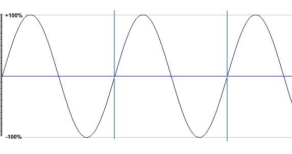
We have to start by establishing the meanings of the terms we will be using from here on in. Creating sound is all about finding new and interesting ways to shove air around. Here is an idealized illustration of what that might look like using a single pure tone.
Using this graphic we can identify some basic units and concepts in sound generation.
The waveform |
The waveform is the wiggly line, obviously! This one is a sine wave. |
A cycle |
The area between the vertical blue lines in the graphic is a single cycle of this wave. In this instance it starts at zero, rises to the highest point, drop back down to zero, continues to the lowest point and rises up to zero again. You can start a cycle at any point of the waveform. It doesn't have to start from zero. The main thing to remember is, if you choose any arbitrary point on the waveform to start from, when you reach that point again, so long as you are traveling in the same direction as you were when you left it, you have completed a single cycle. If you start the waveform at some other point that the one shown here (say, from the highest point on the graph) you have changed the phase of the waveform. It doesn't make it sound any different if you listen to the tone on its own but there are good reasons for being able to change the phase of a wave if you wish. We'll get to them soon. |
Frequency |
Describes the number of cycles in each second. It is measured in Hertz (Hz), one hertz being one cycle per second. If the frequency is in our hearing range we perceive it as the pitch of a note. The human hearing range falls roughly between 20Hz at the low end and about 20,000 Hz at the upper end. If you can hear much higher than that then your owner needs to get you a dog licence. Human ears aren't very good at detecting pitch at the extremes of our hearing range but can be incredibly acute in the midranges. |
Amplitude |
Describes the range of upward and downward movement the waveform makes. We hear it as volume. Large amplitude values mean loud audio signals. Small ones mean quiet ones. If you reduce the amplitude of a wave you are said to attenuate it, if you increase it you are amplifying the signal. These amounts are typically measured in decibels (dB) which are a total pain to work with, mostly because they work to a negative logarithmic scale where minus infinity is the quietest point and zero is the point of optimal loudness. So we'll move quickly past. In a wholly analogue system, like a Stratocaster plus a Marshall stack, amplifying a sound beyond that optimal point gives the desirable sort of distortion sound that has been putting food on guitarists' tables for years. No such luck with a digital system. In the digital world you cannot take the amplitude of a waveform beyond 0 dB. If you try, the wave looks like it hit a brick wall and sounds ghastly! We mention this because putting sound into an amplifier is only one way of increasing its amplitude. Adding another sound source also increases the amplitude of the sound we hear. Which is why a full string section is louder that a solo violin. In sound synthesis it is not uncommon to use several sound sources to create a single sound. The ISE has a built in limiter that manages sound levels internally for you to keep things out of the clipping zone. However, you will need to take some care of levels yourself if you want the best possible sound quality. A limiter working hard is often quite audible which might not be an effect you want to hear! |
Zero crossing |
If you think about it, moving air around systematically involves both pushing it and pulling it blowing and sucking. This is reflected in the graphic in that there is a line drawn through the centre of the waveform. Amplitudes above the line have a positive value, those below have a negative one. In the jargon, audio signals are usually bipolar. The point at which a waveform has an amplitude of zero is particularly important in sampling, something we will cover later. But the location of the zero crossing line has a significance in synthesis also. For convenience, we show the zero line in the graphic as bisecting the waveform so there are equal amounts of waveform both above and below the line. Things don't always have to be this way and there are ways for us to move this line up or down. To do so, in the jargon once again, we apply a DC offset to the waveform. As moving this line up or down will make no appreciable difference to the sound of the tone, why worry about it? If an audio signal is what you want, in truth it is not worth bothering with. But, if you want to use a waveform for something other than audio, like using one waveshape to control the parameters of a second then it can be very important. As we might find out later! |
And that's about as much as we need to know about the components of a waveform. But there are a couple of other things we need to touch on to help understand how to synthesize sounds.
Fundamentals, harmonics and the rest.
If you play a note on any tuned musical instrument you will hear an astonishing complexity of sound. But, despite that complexity you will (hopefully) perceive a pitch. That's the fundamental. In all sounds that we perceive as pitched there is one frequency that stands out from all the other noises in there and this is the one the ear uses as the pitch reference. A piano, violin and oboe sound totally different to each other but, if they all play note A4 you will hear three distinctive sounds all having a common fundamental frequency of 440 Hz or thereabouts.
If you listen more closely to the sound of a single instrument playing a single note, once you get past hearing the fundamental you will hear a range of other tones. Some of these work in a musical way and sound rather like chordal notes related to the fundamental. Others have a more uneasy relationship to the fundamental or are completely atonal.
The musical ones are harmonics. They sound musical because they have a very precise mathematical relationship with the fundamental frequency. The frequency of the harmonics are always a whole number (integer) ratio of the fundamental frequency.
Just to confuse matters slightly, the fundamental is also called the first harmonic. So, a tone with a fundamental frequency of 100Hz will have the second harmonic at 200Hz (an octave), the third at 300Hz (octave plus a fifth), the fourth at 400Hz (two octaves) and so on to the limits of our hearing.
The other sounds that you can hear are called aharmonics. These are frequencies that have a non integer ratio to the fundamental. When there are a lot of these present we tend to perceive the sound as clangorous or bell like.
If these three elements were all present in a sound in similar proportions we wouldn't hear a musical note at all. We would hear noise. So, to make musical sounds we need to find some way of establishing a balance between the fundamental, the harmonics and the aharmonics for any given frequency. And that's what synthesis is all about.
There are three major routes to doing this. One is that we can start off with basic sounds that are very rich in harmonics and then use a filter to reduce or remove the ones we don't want. Oddly enough, that is called subtractive synthesis.
We can also do the exact opposite. We can take very simple tones and add them together to create complex sound. Additive synthesis, surprisingly hard to do well.
The third route is a kind of middle way between these two. If the properties of one waveform can be used to vary those of another at audio frequencies, new and complex waveforms can be generated. You could call this synthesis by modulation. The most common methods used are amplitude modulation and frequency modulation.
In reality we mix and match, using elements from all three main routes as we need them.
Blocking it out
The components of most synthesizers can be categorized into four broad groups.
The first group could be called sources. These are the devices that produce the raw sound you will work with. The ISE allows you to use samples as sources as well as including some very well featured tone generators.
The next group we can call modifiers. Included here would be envelopes that shape the sound over time and filters that remove or emphasize certain frequencies.
The third group are modulators. They apply regular, repeated change over time to specific sound parameters. The most common of these is the low frequency oscillator, the LFO.
Finally there are the effectors. These are signal processing devices, reverberation modules, delays and so on. Usually they act at the end of the synthesis chain.
It is usual to define the output from modifiers and modulators as control signals; being as their usual job is to control the parameters of other devices in the synthesis chain. In the days of monster analogue modular synths it was considered sensible to use different coloured patch cords for control signals to distinguish them from audio and other signals. When using the ISE it is also important to distinguish control signals from the audio path. We'll explain why in a moment.
For now, let's have a look at the first three device types in turn.
The right wave for the right job
Any self-respecting synthesizer will have a tone generator offering several basic waveforms as a starting point for sound creation. Why? What distinguishes one waveform from another? The answer lies in the harmonics on offer. So lets just quickly run through the more common waveforms and see what distinguishes one from the other.
Sine wave |
Is a pure tone. It has no harmonics at all so there is not much point in applying a filter to one. Nothing to filter! This purity of tone make it very good for adding low end definition or kick to a bass sound. It is also good for additive synthesis where you don't want harmonics unless you put them there yourself. Put three or four of these waves together for an instant electronic organ type of sound. |
Sawtooth wave |
Is the most harmonically rich waveform in the box. Characteristically bright and buzzy. The starting point for thousands of classic synth sounds. A sawtooth wave has every harmonic present (theoretically) but their amplitude decreases from that of the fundamental by 1/the harmonic number. So the second harmonic is ½ as loud as the fundamental, the third harmonic is 1/3 as loud as the fundamental and so on until you hearing fails. |
Triangle wave |
Really just a sine wave straightened out. It doesn't have many harmonics and those that are present are quite high up. So, if you want hard and aggressive sounds this is not the wave to choose. Nice for flute sounds and soft leads though. |
Square wave |
A bit complex this one. A graph of a true square wave looks rather like a child's drawing of castle battlements.
Square wave is a shorthand way of saying "pulse wave that spends as much time at the highest point as it does at the lowest". In this form it has a sound that is usually described as "hollow". The reason is that every second harmonic is missing, there are only odd numbered harmonics present. But this absence of even harmonics only holds true if the time between "high" and "low" in the cycle are the same. If the wave spends half of its time at the top the ratio between the high points and the low points of the waveform is 1:2 and, as we already know, every second harmonic is missing. If we change this ratio to 1:3 (i.e. the wave spends 33.3% of its time at the top) some of the missing harmonics return. We now only loose every third harmonic instead. If the ratio was 1:4 (25%) we would only loose every fourth harmonic. And so on. If there was a way of shifting this ratio in real-time we would be able to hear these harmonics coming and going. We could call it pulse width modulation and use it to recreate classic synth string sounds, all kinds of shimmery pad like sounds and some unforgettable bass tones. Sounds like a plan! |
Combination waves |
Unsurprisingly, combination waves can have the characteristics of most of the above. The ISE includes one waveform that can be "morphed" from triangle to sawtooth to pulse wave. If you've followed us this far you should have realised that this gives you the option of tailoring the harmonic content of the waveform quite closely; a very powerful option indeed. Similarly, being able to change the shape of a wave in real-time can open the door to a whole new bag of sonic tricks. Pulse width modulation on steroids! |
Envelopes
Envelopes give us a way of shaping a sound in time. Every synthesizer will always have at least one to control the amplitude of a signal. More sophisticated synthesizers will have several envelope generators which can be assigned to control other important parameters.
Envelopes are usually "one-shot" devices. An event triggers their start and, once underway, they transmit values that correspond to the envelope shape until they are done. They then do nothing until they are triggered again. Amplitude envelopes are usually triggered by the equivalent of a note being pressed on a keyboard.
Envelopes can be described by the stages they go through. The ISE amplitude envelope is a multi-stage envelope, having separate stages for Attack (how quickly the envelope moves from zero to maximum), Hold (how long it stays at the final attack level), Decay (how quickly the level falls to the..), Sustain (the lowest possible level during a note event) and Release (how long the sound will take to fall to zero from wherever it was when the note event stopped). There is a set of stages associated with when the note stops.
The control signals sent by the envelope unit in the ISE can be bipolar; i.e. the control signal value can be positive or negative. This has got some implications if you want to combine control signals from more than one device.
Say you want to combine the output from an envelope and a LFO to create a LFO that fades up or down. As these could both be bipolar signals, shoving them into an adding unit (a simple mixer) won't work as you expect. Adding a minus value to a positive one is subtraction by another name so doing this will result in periodic signal cancellations and other unexpected behaviour.
If you recall your basic grade maths, you'll remember that a negative (minus) value multiplied by a positive always gives a negative result. So, if you want to combine bipolar control signals, use a negative scaling factor on one or more of your control-rate junction input scale factors!
Filters
Amongst some synth nerds, filters can acquire a mythical status, becoming objects to be worshipped or argued about into the small hours. This is rather off-putting for the rest of us and obscures the fact that, from a users point of view, they are actually rather simple devices.
There are only four things you need to know about a filter; its shape, its slope, its cutoff point and whether it is resonant.
The shape is usually what gives the filter its name. So it is a safe bet that a low pass filter will allow low frequencies through and exclude higher ones. Similarly, a high pass filter will do the opposite. A band pass will allow through frequencies that fall into a certain range and a band reject will allow everything through except frequencies in the defined range. Nothing mysterious about that.
The cutoff point is the frequency at which the filter will start to do its stuff. So a low pass with a cutoff point of 600Hz will start to attenuate anything over 600Hz but leave all the lower frequencies alone.
The slope of a filter simply determines how sharp the attenuation will be. It is sometimes expressed in dB per octave and sometimes in "poles". The famous Moog filter had a 4 pole slope which equates to a reduction of 24dB per octave. If the earlier example of a 600Hz lowpass cutoff was a 4 pole type it would mean that, by the time we got to frequencies of 1200 Hz they would be attenuated by 24dB compared to the ones at 600Hz. This is quite a steep reduction and would leave very little audible signal by the time we got beyond 1500Hz. Something more gentle, like a 2 pole slope would only attenuate frequencies by 12dB per octave. So you would hear more of the higher harmonics.
Filter resonance (sometimes called Q for reasons that don't matter) is also pretty straightforward. All this does is emphasize the frequencies around the cutoff point. It is a kind of feedback loop. The higher the Q the more pronounced are the sounds at the cutoff frequency. On some old analogue synths you could crank this up so high that the only thing you could hear was the cutoff frequency so the filter would start to behave like an oscillator. This was called self-resonance. It is not so easy to do in a digital system.
And that's filters really. If they were fix and forget devices they would be little more than glorified tone controls. But, if we can use envelopes or LFO's to change the cutoff frequency or resonance in a dynamic way, then they are the heart of a subtractive synthesis system. Hence all the attention they get.
Modulators Part 1 Slow and gentle
We've made passing reference to it before but it is now time to get into some detail about modulation. It is a huge topic because there are so many possibilities. The skillful use of modulation techniques is probably the single most important factor in getting dynamic, expressive, musical sounds out of a synthesizer.
We'll start with a definition. In synthesis, modulation is the process of using one signal to apply regular, usually cyclical change to one or more parameters of a second signal. Lets look at a simple practical example.
A violinist often gives expression to a piece by adding vibrato. When he or she waggles their finger on the fretboard the net result is that they are making small regular changes to the fundamental frequency of the note they are currently playing. We can do exactly the same thing with our instruments.
To create vibrato on a synthesized voice we simply apply small regular, cyclical changes to the oscillator frequency. We do that by routing the output of one, low frequency (i.e. slow) oscillator to the frequency controls of the main, audio oscillator.
The change this will make depends upon the properties of the signal sent from the low frequency oscillator (LFO). And, when we use a LFO as a controller of other parameters, some things that are not important to the sound of a waveform become very relevant indeed.
There are five aspects to a LFO waveform that are important to consider; the actual shape of the wave, its frequency and amplitude, its phase and its DC offset.
Frequency and amplitude are quite easy to come to terms with. The higher the frequency of the LFO the more changes per second will be made. Amplitude is an interesting one. In our violin example, sending a 100% amplitude sine wave from the LFO to the tone generator frequency control would not give us vibrato. It would give us the sonic equivalent of seasickness. You use the amplitude controls of an LFO to determine how much change is to be applied. For vibrato, very small amplitudes around 3% will do fine.
It is useful to be able to visualise the wave shape of an LFO. If we are generating a sawtooth wave at audio frequencies then the direction of the sloping part of the wave is irrelevant to the sound. A wave that has a slope to the left sounds the same as one with a slope to the right. However, if we want to use an LFO to make gradual change to one parameter, then fall down to the beginning and start again, we would not want to use a waveform with a left facing slope. Visualise it!
Phase and DC offset are related to some degree. Lets consider phase first.
In the vibrato example, for the main oscillator to remain in tune we need the LFO to start from the zero crossing point. If it started at any other place it would automatically add something to the main oscillator and cause it to sound out of tune.
There might be other occasions when we want the effect that comes with starting the LFO at somewhere other than zero. In those circumstances we would adjust the phase to suit our purpose. Again, the best advice is to try to visualise what you want to achieve, then program it accordingly.
Finally there is the DC offset for the LFO. To go back to our violinist (for the last time, honest!) a vibrato effect that shifts the fundamental pitch up and down by equal amounts is not very natural sounding. It actually sounds far more realistic if we push the frequency in one predominant direction. The way to do this with an LFO is to shift the DC offset.
Think about it like this. The LFO is sending numerical values out to be added to the frequency of the main oscillator. As a bipolar signal with no DC offset, half of these values will be positive and half will be negative. Changing the DC offset will shift this balance. If we only want the vibrato to work up from the fundamental we would need to shift the zero crossing point right down so that the LFO sent out only positive values.
This can be hard to visualise just by applying a numerical offset value so the ISE makes it very easy by giving you an option to set the ratio between positive and negative values transmitted by the LFO using two sliders. Nice!
There is a catch to doing this though. If you change the DC offset it will obviously have a non-zero value. Less obviously, if you sent this DC offset LFO to the pitch control of another oscillator you will automatically add the DC offset value to it, taking the oscillator out of tune! So, if you are shifting DC offsets in this way you need to retune the destination oscillator to compensate.
Exactly the same principles apply when using LFO to modulate parameters other than oscillator frequency. We've mentioned how the harmonics present in a pulse wave change depending upon the pulse width ratio. If you route a slow LFO to modulate the width of a pulse wave type oscillator you get a rich shimmering sort of sound as harmonics come and go that has been the basis for synth string patches since forever. It also gives some astonishing bass sounds in the lower registers. Pulse width modulation was actually hardwired into the infamous Moog Taurus bass pedals so beloved by `70's prog-rockers.
Incidentally, if you are using an LFO to modulate pulse width you will need to attend to its amplitude. Too much modulation and you can get to the stage where there are no harmonics at all - not even the first one! Silence is not always golden.
Modulation by slow, sub-audio oscillators is not too difficult to get to grips with. But there is no rule that says that modulators always have to be inaudible. However, what happens when you crank the modulator signal up into the audio range can get pretty wild. One option is to use a device called a Ring Modulator.
With this device you simply take two sound sources and plug 'em into it. In effect what happens after that is that the first audio signal gets spliced with other signal at the frequency of that second signal. What you end up with is a new signal that consists of the sum and the difference of the two incoming signals. Which is OK if the two are pure sine waves. But if they have harmonics attached...:)
At low modulator speeds a ring modulator just chops up the sound in quite an obvious way. This was how they made the Daleks speak! But at high modulator speeds you can get all manner of crazy, unpredictable effects, especially if the modulator frequency is either fixed or changes in a way not related to the carrier. If you want one of those "car crash in a steel foundry" moments (and who doesn't) head for the ring modulator.
As we are talking about high speed modulation it is probably worth mentioning something that isn't going to work in the way you might think. At this point we need to get a bit technical about the workings of the ISE. Remember what we said about distinguishing control signals from audio signals? Here's why you need to do it.
The ISE is a digital synth (obviously!) so everything going on under the hood has to have a sample rate to work to. In order to save resources for the things that matter, the ISE gives absolute priority to rendering the audio signal at a reasonable sample rate, typically 22Khz on a modest PC. To save CPU time, all control signals are rendered at a very low sample rate. The default rate is 100Hz..
In most circumstances, this low sample rate isn't an issue. You don't need to hear the actual output of an LFO or envelope unit so there is no point in rendering it at CD quality when we can do better things with the resources available. However, it does mean that you can't just stick the output of one tone generator into the frequency control input of another because the (incoming) modulating signal will be interpreted as being a control signal and so will be capped at the control signal sample rate frequency.
Going granular
Granular synthesis is a relative newcomer as a synthesis method, mainly because the tools and processing power needed to do it easily haven't been readily available until recent times. As powerful computers tended to be in academic institutions it gathered a reputation for being "something for the boffins". While the underlying maths might be the stuff of nightmares, the concept of granular synthesis is dead easy. Here goes.
If you take a very small section out of a waveform ( a few milliseconds at most), add an similarly small section of silence and loop play the result at audio frequencies you get an entirely new, and rather complex waveform. The audio content of this waveform will be determined by several different things; the size and content of the original mini sample (the grain), the length of the silence, the nature of the boundary between the two (is it abrupt or does it fade and by how much?) and the playback speed.
If you think about it, this is not a million miles away in principle from good old amplitude modulation. But then we take it to another level!
If you move away from using a single grain to using multiple grains, all with different frequencies, or if we modulate the grain size and/or the grain end crossfades it all gets very strange. You very soon start to generate mutated, wholly original sounds that are not easy to achieve by other means. Which is what the buzz about granular synthesis is all about.
Now we wouldn't be telling you all this if there wasn't a way to do it with the ISE. One of the modules available is a "particle generator" and mainstream this is not! What this module does is generate up to twenty little bits of simple waveforms which are then used as the grains in creating a more complex overall sound. You control a range of the more useful and interesting parameters, most of which can be modulated by other the ISE modules.
What comes out of the business end of this module is not always predictable. It is very easy to get it to generate complex, untuned warbling or twinkling sounds. With a little more effort you can make some breathtaking, animated, tuned soft lead sounds. As it is hard to describe the indescribable the best way to learn about this little beastie is simply to play with it. Think about it as a hands on introduction to chaos theory!
A quick word about hybrid synthesis
The use of "real world" sounds instead of tone generators as the starting point for sound synthesis is hardly a new concept. But it wasn't until the 1980's and the development of affordable digital recording technology that the full potential of this could begin to be realised. The ability to process and manipulate recorded sounds using the familiar shaping and modulating tools is a form of hybrid synthesis.
The simplest implementation of this can be seen in most samplers which basically slap a subtractive synthesis engine onto a digital sample playback device. You can do this with the ISE, no problem. And we will. Later.
But that is more than enough background for this tutorial. We can now take this knowledge forward with us and explore the ISE in more practical terms by starting to build our own instruments within the ISE.
Synth Tutorial 2
Working with the ISE Modular Synthesizer
Launch the Synth & FX Editor. This is the place where you activate and program the ISE ... and where MIDI sound creation for the Intermorphic Sound System (ISS) gets very interesting!
Note that the audio plugin framework that underpins the ISE is an open framework, and has been designed to allow 3rd party developers to create application UIs into which they can plug in their own or other 3rd party sound processing modules, including support for the Intermorphic modules if so required.
When you start using the ISE for a MIDI line, what you have is an independent, non-midi, polyphonic synthesizer The sound generation limitations of MIDI pretty much go out of the window.
The ISE is no lightweight. It has a degree of flexibility that is comparable to the old, monster modular synths. It includes some features that are seldom seen, even on very expensive, "famous name" hardware synths. Inevitably, something so well featured and flexible isn't able to hide its complexity too well so there will be a bit of a learning curve to negotiate if you are going to be able to harness this power in a creative way. This tutorial aims to help you up along that curve.
We won't be creating full pieces of music in this tutorial; instead, we'll concentrate on programming sounds using the ISE.
The Path
To get the best from any synthesizer you really need to have some understanding of the path the various signals take inside it. If you have had some experience of hardware synths you will probably be used to imagining a left to right signal path, with the sound generating oscillators at left hand side and the sound output stage at the far right. The ISE signal path pretty much follows this convention...
It is here, in the Synth Network Editor, that we design the sound for the selected MIDI line. As you add synth units to your sound design, they appear as boxes in the bottom part of the dialog. We sometimes refer to these units as "slots"; you can have as many "slots" as you want, where you insert the various modules and units that, together, will make your synthesizer module. The sound you eventually hear will come only from the audio-rate unit in the rightmost slot. So, if you were to construct the simplest of synthesizers, using one tone generator and a LFO, you would have to put the tone generator in a slot somewhere to the right of the LFO. Put them the other way round and, if it was fast enough, all you would hear would be the LFO!
With the proviso that the sound comes out of the right most unit, the signal-flow is pretty strict in terms of left-right ordering. Signals from one module can only ever be passed to modules that are to the right of it in the design. In practice you must put control-rate units (your controllers and shapers, such as envelopes and LFOs) sound BEFORE the sound generating modules (i.e. before your tone generators). So, if you want to use an envelope to control the output from a LFO, you'll have to put the envelope to the left of the LFO. This does of course help you keep a handle on what your signal path is doing. With practice, you won't be confused.
Control signals are different.
Says it all really.
The ISE makes an important distinction between audio signals and control signals. Here's how it works.
Most signals in the system are "audio-rate" signals; they are rendered at whatever sample rate the platform is running at, for example 22Khz.
The only signals that can be used to modulate parameters of a synth unit (e.g. to amplitude or wave shape) are control-rate signals, that must come from a control-rate unit. To save CPU resources for the things that matter, control signals are rendered at a very low sample rate; typically 100Hz. So, if you try to modulate a parameters between units at audio frequencies the best you are going to get is 100Hz. This is not going to be good enough for specialised applications such as FM synthesis!
The reason that we do this, is that it saves a lot of CPU horsepower; to render subsonic waveforms at near CD quality would be pretty pointless. You don't want or need to hear the direct output of an envelope unit or a slow LFO.
On tuning
A fixed architecture synthesizer with limited flexibility can hide a lot of things from the end user. Because the ISE has been designed for flexibility it is up to you to take care of some of the details to make sure that the results you get are the results you expect. This is particularly the case when making sure your MIDI line is in tune with the others in a piece.
The thing that is most likely to catch you out is when you use a LFO to modulate the frequency of a tone generator. If you use the LFO with most of its settings at the default there will not be a problem. However, if you adjust the min or max value sliders you will have a tuning problem that will need correction. Why?
If you recall in the synthesis tutorial, we said that changing these values was the same as applying a DC offset to the LFO wave, i.e. the zero crossing line has a non-zero value! So, if you route a LFO that has been shifted in this way to the frequency of another oscillator you are, in effect sending two values. One is the LFO amplitude, which will change over time and the other is the DC offset which is a constant. This DC offset will have to be allowed for by adjusting the pitch of the sound generating oscillator to get it back into tune.
So, if you have an out of tune MIDI line, check what is modulating the frequency!
Polyphony - a word about resources
All soft synths are serious processor hogs. A lot of effort has gone into minimising the hit that the ISE will make on your processor but you can't cheat physics. Making complex sounds in realtime means doing hard sums very fast and there will be a limit to the strain your CPU can take.
Note: The polyphony a synth will play with the Polyphony ("Poly") setting in the Network Editor. Note: This setting does not display in FX Networks which have no concept of polyphony.
Tips
- If your piece can use built-in wavetable (e.g. for basic drum sounds), or custom audio samples, then consider using them where possible rather than the modular synth. Remember that sample-based drum sounds can be very effective.
- Very importantly, use a polyphony value that is as small as your piece can get away with!
- If you wish any FX to apply to all Cells in a Track, to save processing cycles put them in Track FX (see the Network Editor) rather than directly in your synth module design.
- Be economical with units. Think about ways in which you can maybe use one unit more than once in a voice.
Finally, a word about polyphony. With the ISE, each MIDI line can become an independent, polyphonic synthesizer.
But rather than always thinking of the ISE as a polyphonic synthesizer, you can think also think about it as a synthesizer that can have multiple instances of a Synth Network. If you set the "Poly" parameter to 2 or more, what the ISE does is create the corresponding number of identical synth networks that can operate simultaneously, one for each possible note. So, setting your "Poly" parameter high is an excellent way to use up your processor resources - which you will want to try to conserve. Use it with care.
OK, enough of the preliminaries. Lets get on with making some sounds. The terminology and concepts we will be using will assume you are up to speed!
Simple subtractive synthesis
This is how to set up the ISE as a simple two oscillator synth in the classic style. We'll go through this in some detail because, once you have got the principles of the ISE established, working in more adventurous ways gets much, much easier.
Firstly, we need to create a piece. From Wotja create an new mix (Menu > New) and from the popup Template list Seed (Pak) > Ambient. You will then have a mix or piece that will play long notes. Save this piece as "MyTest".
Launch the Synth Network Editor and set the poly to be 1 or more. Once you set a tone generator in your synth module design, this will then override any MIDI patch settings that your piece is using.
So: we need to design the module that our MIDI line will use. As we are going to make a classic kind of synth we will need two tone generators, a filter and an envelope to control it.
Add the following by tapping on a blank area in the Synth Network: Unit 1 - "Ctrl-Envelope", Unit 2 - "TG Oscillator"; Unit 3 - "TG Oscillator"; Unit 4 - "Filter".
Using an Audio-rate Junction
Hold on - the filter is only fed from the output from the unit immediately before it; and what we really want is to feed the filter with the combined outputs from units 2 and 3! To do this, we need to route the two tone generators into the filter unit. How we do that is fundamental to getting the ISE to work for you!
Tap/hold Unit 4 (the Filter) and press the "Add Before" button and then select a "Junction"; your Filter is now moved to become unit 5! When the Junction Unit is selected, in the bottom Connector & Controllers area tap the Add button twice. Make sure that the first input item of the two inputs you've just added comes from Unit 2 (the first tone generator), and make sure that the second of the two inputs comes from Unit 3 (the second tone generator). You can set relative scaling factors for the two input units by playing with the scaling factors.
Here is the text that we get if we now press the "Export" button on the synth module editor window (we could subsequently reimport this if we need to by highlighting the text, copying it and pressing the "Import" button):
<fxm>
<unit t="c/envelope" r="c"/>
<unit t="tg/osc"/>
<unit t="tg/osc"/>
<unit t="j" i="2,1.;3,1."/>
<unit t="filter"/>
</fxm>
The audio-rate junction you've just added takes the the signals from the two tone generators, and adds them together. The output from your audio-rate junction automatically feeds the filter unit to its right.
OK, that's the network built. Now lets fine-tune our settings.
Tap unit 2 to display the Oscillator Unit. There is a list control where you can select the wave shape for this tone generator. We want a saw wave. The direction of the slope isn't relevant. Close unit 2, then tap unit 3 to display the second Oscillator Unit.
Select a sawtooth wave for the second tone generator. Please make sure its direction is the same as its twin in unit 2 or else they will cancel each other out and you won't hear much! :)
To make a big sound, set one of the tone generators to work an octave lower than the other. You can do this with the one in Unit 2 by setting the Octave offset to 1.
Once you've done all that, tap unit 5 (the filter) to open the Filter Unit. Set the filter type to "low pass" and adjust the cutoff frequency and Q (resonance) to taste. The filter will automatically sweep unless you tell it otherwise.
Here's what the exported module now looks like:
<fxm> <unit t="c/envelope" r="c"/> <unit t="tg/osc"p="1280=2;1287=1;1030=1;1031=1;1026=0;1033=0;1034=0;1028=400000;1281=1.;1282=0.;1283=50.;1284=50.;1285=50.;1288=-1.;1289=1.;1035=0.;1040=0;1042=10;1044=10;1046=50;1048=10;1050=0;1052=400;1054=100;1056=50;1058=0;"/><unit t="tg/osc"p="1280=2;1287=1;1030=1;1031=1;1026=0;1033=0;1034=0;1028=400000;1281=1.;1282=0.;1283=50.;1284=50.;1285=50.;1288=-1.;1289=1.;1035=0.;1040=0;1042=10;1044=10;1046=50;1048=10;1050=0;1052=400;1054=100;1056=50;1058=0;"/><unit t="j" i="2,1.;3,1."/> <unit t="filter"/></fxm>
Next, lets use the control-rate envelope (unit 1) to modulate the frequency of our first tone generator (unit 2). Select unit 2, and and in the bottom "Connectors & Controllers" area add a controller by pressing the "Add" button. Set the source Unit to be unit 1 (our envelope), and set the Param(eter) to be Frequency. Your envelope will now be modulating the frequency of your LFO! Use the Scale slider to adjust the amount of modulation. Select unit 1 if you want to modify the shape of your envelope.
Note that the envelope editor display might look a bit complex to start with, but it it's not really. It can be used to send out negative as well as positive values (it is bipolar!).
For example, you might want an envelope shape that rises slowly to a maximum, falls down to a low level rather slowly and tails off to nothing once the note has ended. So you could set the attack time to around 5 seconds, the decay time to just less than 4, a very low sustain level and a release time of half a second.
Once you have an envelope shape you like it is then just a matter of playing around with things until you get the exact sound you want. Note that you can also use control-rate LFOs to modulate parameters; and many units have a large range of parameters that you can experiment with modulating.
Anyways, back to our example: you should hear a more familiar, if rather overused, sound. If you go back to one of the tone generators and tweak the "Micro Offset" value a bit you will find that fattens up the sound nicely.
For a final touch you might want to add some reverb. This is best done by using it as a global effect for the entire piece because you might have several voices that you want to treat similarly.
If you close the Synth Network Editor you'll be back to the main application window. Press the "Global FX" button to open the FX Network Editor. This looks and works just like the Synth Network Editor you saw before, but this is now being used to edit global FX for the entire piece. Make sure to add an FX of type "reverb", and change the settings in the unit to get the sound you want. Then, close the Unit.
And there we have it. One classic, filter swept pad in the traditional subtractive style. Easy!
Now we have a sound that works it is a good idea to save it for use in other pieces. As noted above, you can export & import data directly via the clipboard and a text editor at various levels of the tool; this makes copying sounds around from piece-to-piece very easy.
If we export the settings from the Synth Network Editor the text should look something like this (depending on exactly what you did!). We need this by the way for our next tutorial step.
<fxm><unit t="c/envelope" r="c"/><unit t="tg/osc" p="1280=2;1287=1;1030=1;1031=1;1026=0;1033=0;1034=0;1028=400000;1281=1.;1282=0.;1283=50.;1284=50.;1285=50.;1288=-1.;1289=1.;1035=0.;1040=0;1042=10;1044=10;1046=50;1048=10;1050=0;1052=400;1054=100;1056=50;1058=0;" c="1#1029,.058"/><unit t="tg/osc" p="1280=2;1287=1;1030=1;1031=1;1026=0;1033=0;1034=0;1028=400000;1281=1.;1282=0.;1283=50.;1284=50.;1285=50.;1288=-1.;1289=1.;1035=0.;1040=0;1042=10;1044=10;1046=50;1048=10;1050=0;1052=400;1054=100;1056=50;1058=0;"/><unit t="j" i="2,1.;3,1."/><unit t="filter"/></fxm>
Waveshaping
This sounds similar in some ways to Voice 1. But this time, instead of using a filter module to remove harmonics and animate the sound we will use an envelope to change the waveform shape over the duration of each note.
If you recall some of the things we covered in the previous tutorial you will realise that changing the waveshape will change the harmonic content of the sound. And, if we get it right, we'll end up with something that sounds like a traditional filter sweep without the CPU hit that the filter involves. So, really, we are almost using additive methods to make this sound. And it is more economical. Great!
Go back your piece above and open it.
Select the filter unit and press the Delete button to remove it. The last unit is now the audio-rate juntion unit, which just adds the two tone generators together.
Open up the Editors for the two tone generators. Change the wave type for each of them to STS. You'll notice that you get some interesting control sliders for this wave type.
Here is the synth module definition at this stage:
<fxm><unit t="c/envelope" r="c"/><unit t="tg/osc" p="1280=5;1283=41.;1284=32.;1285=36.;1048=10" c="1#1029,.058"/><unit t="tg/osc" p="1280=5;1283=44.;1284=57.;1285=59.;1048=10"/><unit t="j" i="2,1.;3,1."/></fxm>
It may not sound that interesting so far, but the STS wave is one of the quietly outstanding features of the ISE. If you couple that with modulation, and keep going, you will see why. The three parameters, controlling the up/down ratio, squareness and slope give you the capacity to morph a waveshape.
It might be a good idea to set up a simple voice just using this waveshape in a single tone generator and play around with the sliders to get the feel for what you can do with this. Basically, if you set the up/down to 100%, squareness to zero and right/left% to either 100% or zero you will hear a sawtooth wave. If you now move the right/left slider towards the centre you will hear the sound mellow until, at 50%, you get a triangle wave. Now move the squareness slider and you hear the sound harden again as the wave become more pulse like. We already know that changing the up/down ratio of a square wave (the duty cycle) will change the harmonic character in other ways. Check it out!
So, by varying these three parameters in different ways in real time you can generate some excellent harmonic changes without resorting to a filter. Lets do it!
We don't need to change the current Envelope settings, but you can play with this if you like. But we do want to route the envelope controller (unit 1) to the appropriate destination!
In the bottom Connectors & Controllers area, for both units 2 and 3, add a controller from unit 1. Ensure that this new controller is used to modulate the Up/Down Ratio parameter. Now do this again, adding new controllers, but this time to use unit 1 to also modulate the Squareness Ratio. Then do this again for the Slant ratio!!
As this is the "suck it and see" school of synthesis, the next bit is down to you and your ears. Hit play and adjust the settings levels on these parameters, the envelop and the scale factors)until you get a sound you like. You'll find that if you overdo the levels you can flatten the waveshape out and lose the sound altogether.
Here is the synth module definition at this stage (it is worth a listen):
<fxm><unit t="c/envelope" r="c" p="1042=0;1044=0;1046=4168"/><unit t="tg/osc" p="1280=5;1283=31.;1284=57.;1285=31.;1048=10" c="1#1029,.016;1#1293,.457;1#1290,1.679;1#1294,-1.251"/><unit t="tg/osc" p="1280=5;1028=5900;1283=28.;1284=41.;1285=35.;1048=10" c="1#1293,.661;1#1294,.533;1#1290,.771"/><unit t="j" i="2,1.;3,1."/></fxm>
It shouldn't take you too long to find settings that sound like the filter sweep we created in the first example. If you check this sound with the one from the first example with a Filter Unit you'll find that this approach actually gives you a greater range of harmonics than using a simple filter. The sound will tend to be richer and brighter, sitting up in the mix more perhaps.
Gentle Ring Modulation
We can use the ring modulator mode of the "osc" unit to give some quite pleasant quality tones that are very similar to those you get from basic amplitude modulation. The key is to make sure that both the tone generators track the pitch of the composed notes.
A ring modulator has to have two inputs for you to hear anything. If you just load up the ring modulator on its own you'll hear nothing. The ISE oscillator use the internal oscillator as one permanent input. All you need to do is route another source into the ring modulator and off you go.
Change one of your modules such that it is one "osc" unit followed by another "osc" unit. Be sure to check the "ring-modulate?" checkbox on the second unit; verify that the "Use MIDI Notes?" checkbox is also checked.
If you play with the various oscillator parameters you'll discover that the harmonic content of the sound generated depends mostly on how far apart the two tones being modulated are.
Ring Modulated weirdness
Go back to your Ring Modulating unit. Uncheck the "Use MIDI notes".
What you get is a weird, metallic noise! The quality of the noise will depend upon the relationship between the frequency coming in from the tone generator and that of the oscillator in the ring modulator. Adjust this frequency until you get a cleaner, bell like tone. It should be somewhere around 700 Hz.
If you want things to get dafter, add a control-rate LFO "(c/lfo") to modulate the ring modulator's oscillator frequency. Try this. Add a control-rate lfo ("c/lfo") as the first unit. Set the wave type of this LFO to Random and the type to Step. Set the frequency to 2 Hz. Now add this unit as a modulator controller of the ring modulator frequency. Hit play! :)
What you should be getting now is weird, randomized electronic chime noises that change every half second. Strange, isn't it?
You can use SF2 samples as the source as well as another ISE module so you can do ring mod sound warping to your own samples in realtime. And who wouldn't want to do that?
Particles. Making ring modulation look ordinary
Now if you thought ring modulated noises were strange, check out this option. As an alternative to a comprehensive tone generator module, the ISE includes the Particle generator.
The concept is based on granular synthesis. This module generates little wavelets of sound punctuated by little sections of silence. With careful control of the comprehensive set of parameters on offer you can generate the most unworldly sounds.
A little alert before we start. This module does a lot of maths! Don't overuse it in a piece or there won't be much processor time left for anything else.
We'll use it to create an Sci-fi movie background music sort of thing.
Open the "MyTest" mix/piece you created above, and delete the Synth Network you made. Add a Particle Unit as your only unit for MIDI line 1. And that's it! :)
Well, not really. The difficulty now is that this all gets very subjective and rather hard to write about. You just need to hit play and then adjust the many parameters on offer in the Particle module until you get a sound you like. So instead lets just check out the key variables.
The harmonic parameter is one of the most influential factors on the end sound. Low values will keep the base frequency of wavelets close to each other. Larger values will mean much greater differences between individual wavelets and a much wider harmonic range to the sound.
Frequency velocity is like a mini pitch envelope applied to each wavelet. Small values give nice detunes and sweeps. Larger values can cause queasiness!
The attack, sustain and decay parameters are like a mini amplitude envelope for each wavelet. Small values make each wavelet distinct and audible. Larger values will cause a smearing and blending of the sounds which is not unpleasant.
Pause governs the time between each wavelet.
The "Number of Elements" value sets the number of wavelets to be generated. Set this lower and reduce the processor hit for this module.
You will hopefully have noticed that every parameter can be modulated by another unit, so there is plenty of scope to sculpt some quite unique and complex pieces with this little baby!
This is just one kind of the strange little things you can get out of it (it is worth a listen):
<fxm><unit t="tg/particle" p="1280=1046;1281=.297;1282=.175;1283=.379;1284=0.;1285=.033;1286=0.;1287=.181;1291=9"/></fxm>
DSynth - The Drum Synthesizer
This one is a little bit different because, with this beast, you can achieve so much. So some explanation is in order first.
To make decent percussive sounds using a modular synthesizer takes quite a few modules, most of which would be rather over specified for the task to hand. Such an approach would waste a lot of computational resources. So we took a different path.
The drum synth module incorporates just the tools you need to create a huge range of tuned and untuned percussive sounds with no waste. It looks a bit complex at first sight because it packs a lot into a small area of screen but once you get the hang of it you'll love it.
The module incorporates three tone generators – two generate sine waves, one generates coloured noise. The noise generator has a multi-type resonant filter. Each tone generator has its own simple attack/decay envelope that controls the amplitude. This envelope can also be routed to control pitch in the case of the sine wave generators and the filter cutoff frequency for the noise generator.
The output of the three generators is added together so you control the mix between them using the envelope level parameter. A word of warning – this module has been designed to kick - it goes loud.
One sine wave generator is designated the master and can be set to any frequency from the low 40’s to about 900 Hz. The other sine wave generator slaves to this frequency, i.e. its setting is a ratio of the frequency of the first one. We do this mostly to save CPU resources (the slave oscillator’s maths are slightly less taxing)
One thing worth noting is that the two sine wave generators can cross-modulate the other’s frequency. What’s the point of this?
Well, using the output of one sine wave generator to modulate the frequency of the other will give some metallic-like tones. It is called frequency modulation synthesis. Exactly how metallic will depend upon the difference between the frequencies of the two generators and on the depth of the modulation.
If you then take that modulated output and make a loop so it modulates the frequency of the first tone generator (modulate the modulator as it were!) then the results can get even more harsh and chaotic. At high modulation depths this is just what you need to start to create struck metal percussive effects. Lower depth values will dirty up drum sounds for you rather nicely.
You can force this module to track composed note values. There are loads of possible uses of this feature. The obvious one is to get several percussion instruments for the price of one. If you want to set up an alternating high/low cowbell figure simply load up the relevant preset, enable note tracking on this module and set up a pitched fixed voice type or something similar to take care of the tuning. You can also create a whole battery of tuned percussive instruments; marimbas, bells by using this option.
Enjoy!
And that just about concludes this quick jaunt through the practical application of the ISE. We've really just scratched the surface but hopefully you have collected enough pointers from this and the previous tutorial to make your own way from here.
External Links
Glossary
Tone Generator (TG) Unit : A unit that knows how to generate sound in response to MIDI note events. These are the Wavetable, DSynth, Oscillator and Particle units. You can have as many TG Units in your design as you want, subject to the processing power of your target platform.
FX Unit : An audio processing stage which can be used to perform a variety of exciting things. You can have as many FX Units in your design as you want, subject to the processing power of your target platform.
Synth / FX Network: A grouping of all units used by a particular Synth or FX (Global FX or Track FX). Think of it in terms of a row of audio-rate units that work from left-to-right.
Audio-Rate Unit : An unit that works at the normal audio processing rate of the system, e.g. Wavetable Unit.
Control-Rate (Ctrl) Unit : A unit that works at a lower rate than the normal audio processing units and is used to control parameters on other units. These are the Ctrl-LFO, Ctrl-Envelope and Ctrl-Amp units.
LFO: Low Frequency Oscillator. The Ctr-LFO Unit can be used to control other effects unit parameters such as filter cutoff frequency or perform pitch modulation. The audio-rate LFO (Osc) can be used as a direct frequency generator, or to apply Ring Modulation effects if run at a low enough frequency.
Envelope: A Control-Rate Unit that creates a waveform in direct response to a note on MIDI event; used to modulate various critical parameters within audio-rate or control-rate Units. For example, envelopes are used to shape the volume of a note when it is triggered, and can also be used for all sorts of neat effects such as modulating the pitch of a note while it plays.